Fiber Optic Bend Radius Calculator
Estimate minimum static and dynamic bend radius, bend diameter, enclosure slack loop length, bend-loss risk, and derated pull tension for common home fiber routes.
1.Fiber routing presets
2.Cable and route inputs
Fiber bend radius result
3.Fiber cable/spec grid
4.Fiber bend reference tables
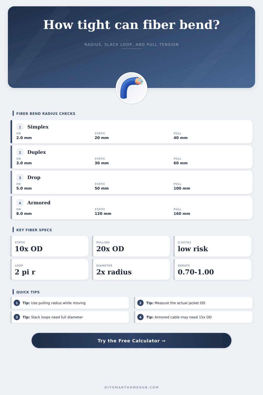
| Cable/spec profile | Typical OD | Static radius | Dynamic radius |
|---|
| Fiber type | Bend-loss sensitivity | Risk factor | Planning cue |
|---|
| Routing preset | Cable choice | Check mode | What to watch |
|---|
| Route derate | Radius factor | Tension factor | Use when |
|---|
5.Planning tips
Bend an optical fiber too far and the signal dissapears into the cladding. Pull back a little more of the coating, and there’s the light, going strong along the glass inside. That’s the physics: bending loss. And it makes what was once a high performance network link into a dead end. Somebody routed a jumper around a sharp corner without checking the math.
Before you start pulling wire through walls or drilling holes, this calculator helps you guess if your intended route are within those physical limits. There are basically two state to consider. The static state is when the cable has been installed or is lying coiled in a box somewhere. The dynamic state is as you move it along and under tension, typically during installation.
Why Fiber Bending Radius Matters
Obviously, one doesn’t want any sharp kinks. What most installers don’t realize is exactly how much room they should of allow for both conditions. Under dynamic conditions (e.g., pulling the cable along under tension) there’s almost always more space needed. This happens because the pulling force and friction together create more stress in the glass than it can handle at smaller curves. You’ll get the cable into the conduit if you’re planning your run to match the static limit, however you might find that it breaks or won’t carry a signal when you try to arrange it neatly in the cabinet.
Diameter matter, and outside diameter is more important than you think. Even though both cables might have the exact same kind of fiber, a thick armored riser cable require much more space to turn than thin simplex patch cord. To account for this, the tool allows you to specify the profile of your cable. It automatically calculates your baseline multipliers based on your selection.
As you can see, often static conditions has the min radius being ten times the diameter of the cable. For pulling situations, it’s 20 times. Those aren’t random numbers from a book… Those are safety margins to avoid micro-bending. Micro-bending is when tiny deformations in glass cause the photons to leak out. And the leakage occurs slowly. It’s difficult to notice and before long, you’ve dropped your link budget down to unsustainable levels. This is why it’s so important to plan for it.
There’s more to it as well, fiber type. OS2 (a rigid, single mode fiber) is not good for bending. G.657 A2 (newer bend insensitive types) is designed to handle tighter bends with minimal loss of light. Choosing the correct glass type can be the difference between a successful link and a failed one if you’re installing fiber behind drywall or in a small server room. Space is at a premium and choosing bend insensitive fiber can make the difference between a clean install versus a failed link.
These sensitivities are outlined in the reference tables on the page, they are used to match your environment to your hardware. Bend-insensitive fiber doesn’t have to be everywhere, just in tight spots. It makes sense there.
Special mention goes to slack loops, which cause most of the trouble. A length of excess cable held in a box or on a tray becomes an eternal curve, no longer capable of relaxing. Because of this, it stay under tension all the time. The diameter around which you keep it must be greater than width of whatever confines it or it will, over time, become weaker…or break.
The calculator considers the diameter (as opposed to radius) headroom necessary for your loops and compares this to what you have available. It tells you that a loop requires diameter space, not just radius headroom. It accounts for connector and strain relief straight allowances too, often overlooked till the day the patch cord won’t quite plug in.
The other variable that multiplies risk is pulling tension. With every turn, bending increase the tension on the fiber inside its jacket. Depending off how many bends it encounters along the way, each one can increase the tightness of the overall pull. The tool also factors in what kind of pulling environment you’re operating in (is it a crowded conduit or an open tray?), as well as length of the route.
Did I mention cold weather makes the jackets stiffer? You have to handle them more carefully. That’s reflected in the derate profiles. It’s a realistic model that considers real-world friction versus idealized lab conditions.
So, again, bending radius is a matter of ensuring signal integrity for decades. It is not simply about transporting the light now. Avoiding a few more inches during installation will cause problems later on as network speeds increase and shrink those margins. Run your unique cable OD and routing constraints through this estimator and make sure your fiber network will be strong against sharp bends.