Cat6 Voltage Drop Calculator
Estimate voltage drop, delivered voltage, cable heat loss, and current per powered pair for low-voltage DC power carried on Cat6 conductors.
These presets model DC power on Cat6 conductors. They do not estimate Ethernet data range, PoE negotiation, or compliance distance.
Cat6 power result
Common solid Cat6 conductor size used for the default model.
Common in patch leads and some flexible cords.
Slim patch cable has much higher drop at the same load.
Resistance correction uses 20 deg C as the reference point.
| Conductor | Resistance at 20 deg C | Loop ohms per 100 ft | Typical Cat6 use |
|---|---|---|---|
| 22 AWG copper | 16.14 ohms / 1000 ft | 3.23 ohms | Oversize or specialty balanced cable. |
| 23 AWG copper | 20.36 ohms / 1000 ft | 4.07 ohms | Solid horizontal Cat6 and Cat6A cable. |
| 24 AWG copper | 25.67 ohms / 1000 ft | 5.13 ohms | Patch cords and lighter solid cable. |
| 26 AWG copper | 40.81 ohms / 1000 ft | 8.16 ohms | Slim patch cable, high drop for power. |
| Powered pair count | Current sharing | Equivalent loop resistance | Use case |
|---|---|---|---|
| 1 pair | 100% of load current per pair | Full pair loop resistance | Small sensors, relays, short test runs. |
| 2 pairs | 50% of load current per pair | Half of one-pair loop resistance | Moderate 12 V or 24 V device loads. |
| 3 pairs | 33% of load current per pair | One third of one-pair loop resistance | Custom harnesses where one pair stays spare. |
| 4 pairs | 25% of load current per pair | One quarter of one-pair loop resistance | Higher DC power with all pairs dedicated. |
| Voltage drop band | Result meaning | Common action | Why it matters |
|---|---|---|---|
| 0% to 3% | Excellent | Usually comfortable | Good delivered voltage and low cable heat. |
| 3% to 5% | Good | Check device tolerance | Often fine for regulated 24 V or 48 V loads. |
| 5% to 10% | Borderline | Add pairs or raise voltage | Low-voltage loads may sag during peaks. |
| Above 10% | High drop | Shorten run or use larger wire | Cable loss and terminal undervoltage become likely. |
| Scenario | Typical voltage | Typical pairs | Planning note |
|---|---|---|---|
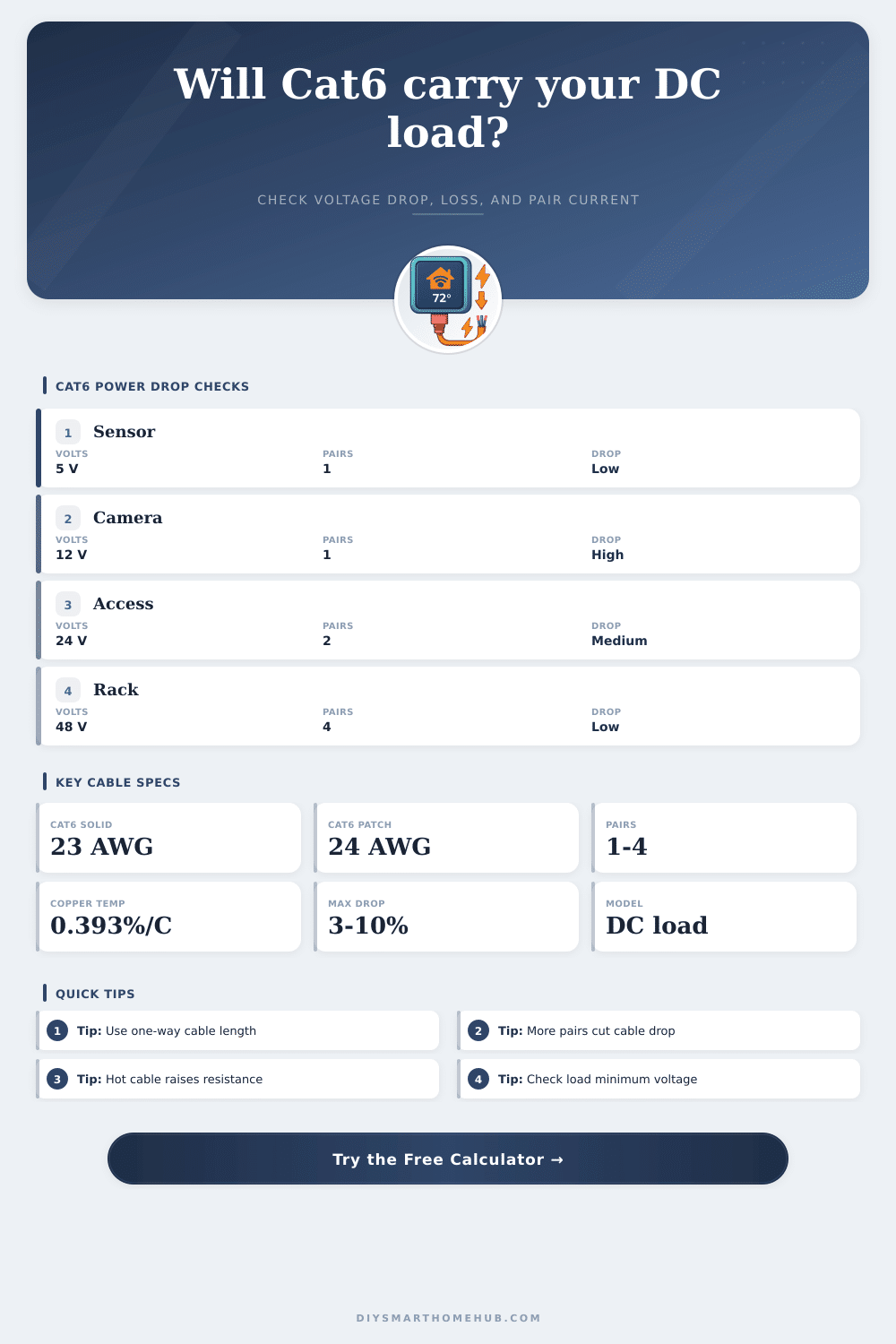
| Small sensor board | 5 V | 1 pair | Short runs only; 5 V has little drop headroom. |
| Passive camera feed | 12 V | 1 to 2 pairs | Check night IR or heater peak load separately. |
| Door reader or keypad | 24 V | 1 to 2 pairs | Better voltage headroom than 12 V at the same watts. |
| Remote DC converter | 48 V | 2 to 4 pairs | Lower current keeps Cat6 loss manageable. |
Security cameras reboots during night vision because of a voltage drop. Weak Wi-Fi isn’t typicaly the problem. Often, the ethernet cable act like a resistor and loses some electricity as heat on its way to the plug. Enter the run length and load, and the calculator does the math for you. It translates airy resistance numbers into an obvious thumbs up/down answer about keeping your device online.
The other thing many folks do is consider only the one-way distance. Maybe they see thirty feet to an outlet and figure that’s all there is. But electricity has to go out and come back in, so that’s twice as far than what you can actualy see. The tool ask for one-way distance, but then it computes based off loop resistance. Your guess will be half of the real world number if you don’t take into account the return path. That means a brownout at the device. It is a little thing, sure. But it makes projects go poorly.
Tips for Stable Power in Security Cameras
Inside Cat6‘s jacket are four pair of twisted wire. Only one pair are used for power on most low-voltage applications. Two little wires becomes a bottleneck as they has to carry all the current. If you’ve got a heavier load, you can offset it by paralleling multiple pairs. According to the reference table, doubling up on active pairs halve the effective resistance. That means less congestion and better flow. Just make sure you have power source that will support the total current of all those strands.
Copper also becomes more resistant to current at higher temperatures. That means that a cable sitting in a hot attic during July will have more resistance than a similar cable in a nice cool server room. The calculator take this into account and allows you to change it. If you make estimates without accounting for temperature, then it’s usually too optimistic (the real world isn’t always perfect). Having some margin for heat ensures you’re covered when the sun is beating down or when gear are jammed tightly into a small rack.
The connectors increases resistance in the circuit. An RJ45 plug and a punch-down block each contributes a slight amount of resistance. A few tenths of an ohm by themselves aren’t much, but multiply that by ten. On a long run? That’s 80 milliohms. Enter the total contact value into the tool. That way, if there’s any voltage lost on junctions, it won’t surprise you. Everything that touches the wire matter, not just the wire itself.
Know your device’s tolerance; know how much voltage your device require and what it will tolerate before failure. Knowing your device’s tolerance is just as important as knowing cable specs. If my sensor is 5 volts, there’s no wiggle-room. Half a volt off, you’re over the cliff. If you have a forty-eight-volt DC converter, you’ve got more wiggle room. That may not be a problem. Understanding this and planning around the limits makes it go from a guessing game to a plan. Maybe you can’t shorten the run but maybe going from single pair to two will keep things stable on the feed. Most often it’s not about having a magic length of wire. It’s about knowing how energy flows through your system before it arrives so you can make adjustments to stay stable with what you have, and you should of planned ahead.