Bluetooth Mesh Hop Count Calculator
Estimate Bluetooth mesh relay hops from path distance, node spacing, TTL, relay density, 2.4 GHz attenuation, retransmit settings, and practical latency limits.
Path geometry, relay spacing, and TTL
2.4 GHz link budget per hop
Message retransmits and latency
Live planning checks
| Planning item | Calculator formula | Typical range | Interpretation |
|---|---|---|---|
| Adjusted path | Distance × path factor | 1.0x to 1.8x | Accounts for corridors, floor changes, and indirect relay placement. |
| Radio legs | ceil(path / usable spacing) | 1 to 10 | Direct link is one radio leg; relays are the intermediate nodes. |
| Relay nodes | max(0, radio legs - 1) | 0 to 9 | Nodes that must successfully repeat the message along the path. |
| TTL budget | radio legs compared with TTL | 0 to 126 | Keep TTL high enough for the path but not much higher than needed. |
| Link budget | TX + gain - losses - sensitivity | 10 to 25 dB | Usable margin after fade and interference penalties is the safety reserve. |
| Environment | Relay spacing | Wall allowance | Practical note |
|---|---|---|---|
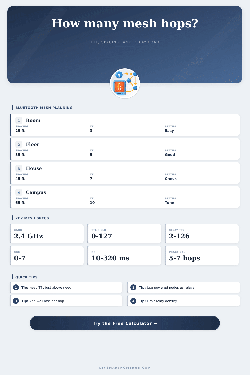
| Same-room lighting | 20 to 35 ft / 6 to 11 m | 0 to 1 wall | TTL 2 or 3 is often enough when relays are visible. |
| Apartment or small home | 30 to 45 ft / 9 to 14 m | 1 to 2 walls | Use powered lamps, switches, or plugs as relay anchors. |
| Multi-floor house | 25 to 40 ft / 8 to 12 m | 1 floor plus walls | Stairwell or hallway relays usually outperform corner devices. |
| Detached garage path | 40 to 80 ft / 12 to 24 m | Exterior wall loss | Outdoor line-of-sight can be good, but wall exits dominate. |
| Dense office corridor | 20 to 50 ft / 6 to 15 m | Many partial walls | Limit relay count to avoid unnecessary flooding traffic. |
| Bluetooth Mesh item | Spec value | Calculator use | Design implication |
|---|---|---|---|
| TTL range | 0-127, with 127 reserved for relay handling | Compares allowed forwarding depth to required radio legs. | Set TTL just above the path need to reduce needless flooding. |
| Relay forwarding | TTL 2-126 can be relayed | Determines whether intermediate relay nodes can carry traffic. | TTL 0 or 1 should be used only for local or direct-control traffic. |
| Network transmit count | 1-8 transmissions | Multiplies source airtime estimate. | More source repeats improve robustness but consume shared channel time. |
| Relay retransmit count | 1-8 transmissions | Multiplies each relay leg airtime estimate. | High relay repeat settings can congest dense lighting meshes. |
| Advertising bearer | 2.4 GHz BLE advertising channels | Used with path loss and wall/floor penalties. | Powered relay placement matters more than absolute device count. |
One light switch is all it takes to begin your smart home. From there, it tend to sprawl across several buildings, inside and out. As that happens, signal gets weaker. One solution are mesh networks, which pass information from device to device in order to close the gap. But to do that right require some forethought.
Should you plan where to put them, or just let them be where they want to go? That’s what makes the difference between a fast response and one that lag. This brings us back to the hop count, the core metric. Every time a message goes via a relay node, it lose one unit of Time To Live (TTL). In the case of Bluetooth Mesh protocols, this rule is enforced very strictly. You send a packet into the mesh with an assigned TTL value, and every relay decrements it prior to forwarding data. Once the TTL hits zero, the message is gone. This put a hard limit on how far the message can go.
How to Plan Your Smart Home Mesh Network
How do you ensure there’s enough TTL budget left for the number of hops required by a message from your bedroom lamp trying to reach a switch located deep within another wall somewhere in your basement? This is where calculator can help you figure out radio range once you define your layout by doing math for you.
What’s on a blueprint is not necessarily what you get in the air. Signal degrades a lot with concrete floors, big pieces of furnitures, and drywall. Rather than just node-counting for distance, planning out how far apart relay points need to be are important.
The other common misstep is assuming battery-based sensors will be able to carry heavy traffic. In almost all cases, this is false. You want to anchor your network using mains-powered nodes such as dedicated gateways or smart switches which can constantly relay packets without impacting their power source. This utility can help you figure out how much of a path you’ll need to cover with powered relays.
The second part of that equation is called link margin. You may have a large number of hops to get where you need to go, but the signal strength must be strong enough in each hop to overcome microwave and wifi interference. The devices runs on the same 2.4 GHz band. A fade margin should of been added to account for background noise. Without adequate margin, the mesh could function when house is empty, but not at peak usage times when everybody’s streaming video and using their phone. That’s missed by most people till it stops working.
Each hop adds latency Bluetooth Mesh relies on periodic advertising events, there is no instant jump from A to B. The message wait until the next open slot in the relay’s transmission schedule. Using multiple retransmits help with reliability, but that delay builds up at every hop. What you discover is that sometimes more relays makes a stronger signal but also add some delay. That delay can be perceptible when talking about lighting controls. In the case of HVAC updates, who cares? Knowing this tradeoff lets you dial in your network priorities to match what these devices realy do.
Generic spacing guidelines like thirty feet are good advice found in reference tables, which assume an open warehouse environment. In reality houses have metal frames and thick walls; those numbers dont apply indoors. Adjusting based off the true shape of your space is what real world planning calls for. You can see this by comparing a direct line-of-sight path versus a corridor path; the latter causes signals to pass through structural elements and to bend around corners. Your house have unique characteristics (e.g., wall loss, floor penalty); plug them into the model so you know where it’s weak.
Relay devices provides redundancy that builds mesh network strength, but too many relays can congest the mesh. Collisions occur when more than one relay try to forward each packet. Balancing coverage with not too many relays is the trick. The calculator let you quickly check how close to maximums you’re running against standard rules. You can see where your chosen retransmission settings or TTL values approaches the limits of the specification. That way you can determine an efficient, yet robust mix of components.
No amount of hardware will build a resilient mesh. A resilient mesh is built through knowledge of those unseen routes that data need to travel. From a troubleshooting perspective, or even a setup perspective for a new smart home, having knowledge of your link margin and hop count at the outset eliminates guessing further down the line. You start with a single switch and finish with a system free from interference.