LM317 LED Driver Calculator
Size an LM317 constant-current LED driver by resistor value, LED string voltage, supply headroom, regulator heat, and resistor wattage margin.
LM317 Driver Results
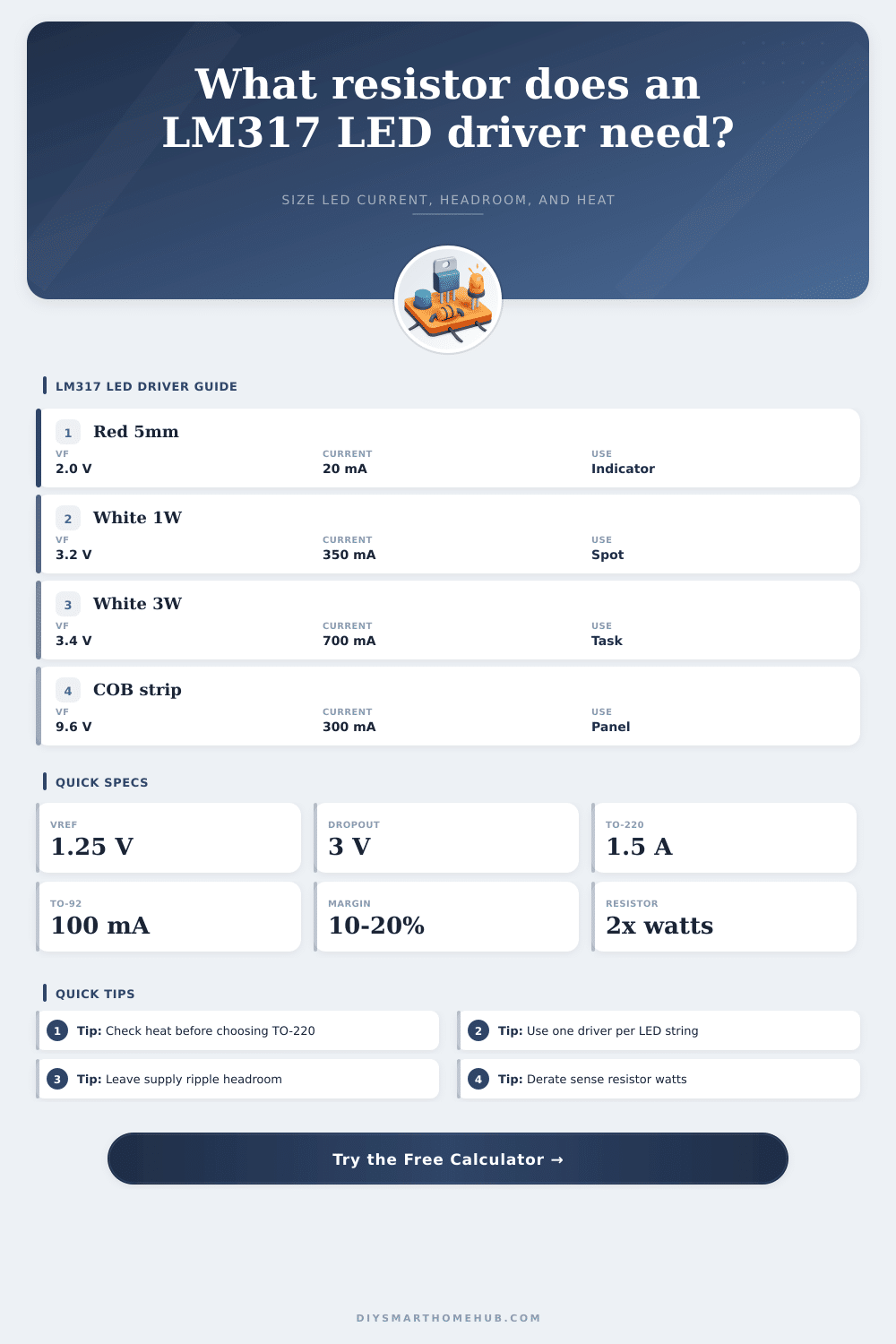
| LED Type | Typical Forward Voltage | Typical Current | LM317 Design Note |
|---|---|---|---|
| Red 5 mm indicator | 1.8 to 2.2 V | 10 to 25 mA | LM317L can work, but resistor power is usually tiny. |
| White or blue 5 mm indicator | 2.9 to 3.4 V | 15 to 30 mA | Good for stable brightness from changing supply voltage. |
| 1 W white emitter | 3.0 to 3.5 V | 300 to 350 mA | TO-220 package normally needs airflow or a small heatsink. |
| 3 W white emitter | 3.2 to 3.8 V | 600 to 750 mA | Heat is often the limiting factor, not resistor value. |
| 9 V COB segment | 8.7 to 10.2 V | 250 to 350 mA | Needs a higher supply because LED voltage uses most headroom. |
| 12 V strip section | 11 to 12.6 V | 100 to 500 mA | Use a supply above strip voltage plus LM317 overhead. |
| Device / Package | Practical Current Range | Thermal Starting Point | Best Fit |
|---|---|---|---|
| LM317L TO-92 | 5 to 100 mA | High °C/W, little heat area | Indicators, small opto LEDs, test loads. |
| LM317 SOT-223 | 25 to 500 mA with copper | Depends heavily on PCB copper | Compact boards with short LED strings. |
| LM317T TO-220 | 50 mA to 1.5 A rated | Needs heatsink as dissipation rises | Bench drivers, 1 W and some 3 W LEDs. |
| LM317HV TO-220 | Similar current, higher voltage rating | Same heat math as standard TO-220 | Longer series strings from higher DC rails. |
| Target Current | Calculated Rsense | Resistor Power | Suggested Rating |
|---|---|---|---|
| 20 mA | 62.5 ohms | 0.025 W | 0.125 W or higher |
| 100 mA | 12.5 ohms | 0.125 W | 0.25 W or higher |
| 350 mA | 3.57 ohms | 0.44 W | 1 W or higher |
| 700 mA | 1.79 ohms | 0.88 W | 2 W or higher |
| 1 A | 1.25 ohms | 1.25 W | 3 W or higher |
| Project Scenario | LED String | Supply | Typical Result |
|---|---|---|---|
| Small status lamp | 1 red LED at 20 mA | 5 V | 62 ohm sense resistor, low heat. |
| Cabinet puck | 1 white 1 W LED at 350 mA | 9 V | 3.6 ohm sense resistor, heatsink check needed. |
| Desk task light | 3 white LEDs at 300 mA | 15 V | 4.2 ohm sense resistor, moderate headroom. |
| Panel channel | 4 red LEDs at 100 mA | 12 V | 12.5 ohm sense resistor, ample voltage margin. |
| Garage segment | 2 high-power LEDs at 700 mA | 12 V | 1.8 ohm sense resistor, heatsink usually required. |
Are you driving an LED? So you know that means plugging in a resistor, right? Well…not exactly. Sure, you can connect some LEDs to a power source through a resistor, but if your not taking care of thermal load, then you’re not creating light fixture; you’re building yourself a toaster with big dreams. The LM317 has been around for a long time because it is reliable; it work well, but only if you use it properly and keep an eye on how much heat it produce.
Once you enter your string information into the calculator above, it’ll do all the number-crunching for you, saving you the hassle of trying to guess values and whatnot as you’re soldering away. As an LED driver, the basic secret is realizing that the LM317 isn’t acting like a voltage regulator here at all (instead), it’s a current source. It maintains constant 1.25 volts across a small sense resistor connected to ground pin. And then there’s Ohm’s law.
Why Heat Is a Big Problem for LED Drivers
25 volts at that current. How many amps? 3.6 ohms. Simple math. But the devil is in the detail, especially when you’re dealing with things involve heat.
25 volt drop. The LM317 drops almost 5 volts, only leaving 4 volts for the LED. That means over 1.7 watts of dissipated heat that has to go somewhere. Those watts adds up quick. A TO-220 package feels nice and strong in your hand, but it’ll be cooked in minutes at that power level without a heatsink. You can tinker with your proposed heatsinks using the tool on this page.
This tool lets you set thermal resistance and ambient temperature to see whether or not it’s realy doing what it should of. If your estimated junction temperature is rising towards 125 degrees Celsius, it’s got a problem before you’ve even turned it on. That is what most hobbyist fail to account for. They account for current by sizing the resistor but they don’t account for voltage headroom needed to maintain a cool and stable regulator.
The other part of the puzzle are the LED string configuration. Forward voltage on white LEDs tends to be pretty high (around 3 volts each). This means if they’re powered at a lower voltage such as 5 volts, there’s not enough headroom to allow any but a single LED. Additionally, you don’t want to drop below a couple of volts on the LM317 because its output will vary, causing light to flicker as current changes. To keep things regulated, you really want to run your LEDs in series whenever possible.
When you do this, the current through all of them are shared, so you need fewer drivers to drive multiple LED. With parallel LEDs, you’d need to use some sort of complicated balancing circuit or lots of regulators to keep current sharing proper. In this case “thermal runaway” would cause an LED to become hotter, take more current, get even hotter and eventually fail while starving the rest. To help visualize this tradeoff, the calculator comes with a handy reference table listing typical forward voltage for common package sizes.
While 20 milliamps at 2 volts represents a negligable amount of power, producing no heat, you could drive a 3-watt white emitter, drawing almost 700 milliamps at almost 4 volts, that’s serious thermal management business. That isn’t simply because something is brighter; it’s because there’s more physics involved in how electricity gets converted into light. If there’s one or two watts of electricity that didn’t get turned into light, they have to be dealt with (as heat), requiring aluminum fins, thermal paste and copper traces.
Also think about your source of power. Many 12-volt wall adapters adds ripple due to switching converters and sag when loaded down. The LED will strobe or dim if the input drops out of range of what regulator can handle. This is where adding a safety gap helps protect you from that. It is a small thing, but it can make difference longterm.
In conclusion: When you design with the LM317, just remember, there’s an energy balance. There has to be a place for the waste heat to go when you make light; no getting around that. Use the calculator beforehand so you can see this flow in your mind before it melts some solder joints on your breadboard. Check the thermal estimates, check the headroom, check those resistor values up front so you don’t enter the “let’s try this and see what happens” phase of your project.
Be conservative. Verify the thermal path. Let the hardware do the work. The board will remain cool, and the light will remain bright.