RG213 Coax Loss Calculator
Estimate RG-213 feedline attenuation from length, frequency, connectors, lightning protectors, SWR mismatch, transmitter power, antenna gain, and receive margin.
📍RG-213 feedline presets
📡Cable, radio, and antenna inputs
Full calculation breakdown
📊RG-213 specification snapshot
📐RG-213 attenuation reference
| Frequency | Approx loss per 100 ft | Approx loss per 30 m | Planning note |
|---|---|---|---|
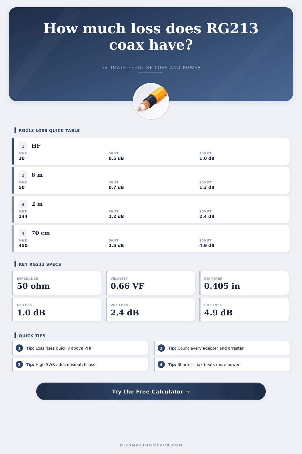
| 10 MHz | 0.6 dB | 0.6 dB | HF runs are usually connector and routing limited. |
| 30 MHz | 1.0 dB | 1.0 dB | Good for long HF feedlines when SWR is controlled. |
| 50 MHz | 1.3 dB | 1.3 dB | Six-meter loss is noticeable on longer tower drops. |
| 144 MHz | 2.4 dB | 2.4 dB | VHF base stations should keep length reasonable. |
| 450 MHz | 4.9 dB | 4.8 dB | UHF performance can be dominated by feedline loss. |
| 900 MHz | 7.3 dB | 7.2 dB | Use a shorter path or lower-loss coax for long runs. |
🔌Connector and accessory loss guide
| Item | Typical loss each | Where it matters | Calculator use |
|---|---|---|---|
| Type-N connector pair | 0.05 dB | VHF and UHF outdoor feeds | Use for well-made weatherproofed ends. |
| PL-259 / UHF pair | 0.08 dB | HF and lower VHF | Raise value for old adapters or poor soldering. |
| BNC adapter pair | 0.10 dB | Scanner and test jumpers | Count every inline adapter. |
| SMA pigtail pair | 0.15 dB | Small radio transitions | Short pigtails can still add measurable loss. |
| Lightning protector | 0.05 to 0.30 dB | Outdoor antenna entries | Enter data-sheet insertion loss when known. |
💻Device and feedline comparison grid
| Coax or device path | Best fit | Relative loss | Recommendation cue |
|---|---|---|---|
| RG-213 / RG-8 style | HF through moderate VHF | Medium | Strong mechanical choice for many base stations. |
| LMR-400 class | VHF/UHF base runs | Lower | Compare when RG-213 loss exceeds the target margin. |
| RG-58 jumper | Short patch leads | Higher | Keep very short at VHF and UHF. |
| Hardline / heliax | Long UHF tower runs | Lowest | Useful when cable loss is more than antenna gain. |
| Remote radio at mast | High-UHF receive paths | Shortest RF path | Moves loss into control and power cabling instead. |
🏠Common RG-213 project examples
| Project | Frequency | Length | Expected RG-213 cue |
|---|---|---|---|
| HF attic dipole | 7 to 29 MHz | 50 to 100 ft | Usually below 1 dB of cable loss. |
| 2 m roof vertical | 144 MHz | 50 to 75 ft | Plan around 1.2 to 1.8 dB before accessories. |
| 70 cm base antenna | 430 to 470 MHz | 50 to 100 ft | Feedline can consume several dB. |
| Scanner receive mast | 150 to 900 MHz | 30 to 80 ft | Receive margin may benefit from mast preamp placement. |
| Satellite rotor loop | 145 and 435 MHz | 60 to 100 ft | UHF side is the loss-critical path. |
💡Coax planning tips
There’s coaxial cable hanging off your shoulder as you stand in the rain on top of a ladder. Is additional length of the RG-213 going to ruin the signal? Can you even hear the other person well enough at this point to complete the contact? If you’ve been a ham long enough, you know what I’m talking about here.
There is feedline loss. This is where theory of an antenna meets real-world conditions. In your hand, that chunky cable appears robust and up to the task. That’s part of how it dupes folks into believing it isn’t lossy.
Understanding Cable Signal Loss
While good for VHF and HF, when frequency increases that fat jacket turns into quite the signal reducer. It’s all pretty complex engineering, but the root cause is just plain old physics. The coaxial cable are essentially a resistor with changing resistance based on the pitch of the radio wave traveling down its path. It is barely perceptible in a short run at thirty megahertz, but if you push it out to UHF territory, that same distance devours watts before reaching antenna element.
Use the calculator above and let it do the math. It knows your exact length, connector count, and frequency. It will tell you exactly how many watts survives the journey from radio to air.
Many ops gets hung up on the output power from the transmitter, which is readily displayed on the radio’s front panel. When signal reports start falling off, they look for the problem in the feedline…only to panic when it’s too late. That’s backasswards logic. It doesn’t matter how much amplifier power you throw into a bad feedline, there are regulatory caps as well as thermal limits that stop you. That’s not where your decision point lies; that happens before you reach for the ladder to go up the tower (or before ordering cable).
A loss of almost five dB for every hundred feet of RG-213 at 450 MHz make a big difference if you’re planning the rest of the station setup. Cables do have attenuations, but connectors sometimes grab the attention. You may spend a few pennies on a PL-259 connector but that bit of oxidation or bad crimp in the barrel can cause mismatch loss greater then the cable’s own attenuation. The tool accounts for these inline elements and reminds us: Each adapter increase resistance to the path. Meters, switches and even lightning protectors adds little bits of loss too and those add up if chained. It’s a game of small losses stacking up to big problems.
We tend to downplay this next point, but standards are everything: Standing Wave Ratio, or SWR, is a measure of how well your rig’s power transfer through the line. In other words, if your SWR is high, your power reflect back toward its source. This wastes signal strength and heats your feedline. You’ve probably heard people claim that SWR doesn’t impact loss because their tuner perfectly matches the radio. However, in the real world, mismatched systems experiences greater overall loss because the reflection keeps bouncing around inside the insulation of the cable. A low SWR is just as important as having a dry line.
Likewise, receiving well is key, particularly with digital modes and/or when working weak signals. Remember, if they’re too faint for your receiver to hear in the first place, it won’t matter how loud you can transmit, as they’ll be drowned out by your own noise floor (receive margin). Seeing this visualized in calculation gives you an idea of where the receiver’s sensitivity levels are relative to what level of signal you might expect to recieve. It changes focus from simply transmitting something to being able to communicate back and forth clearly. This is what you want, because something that transmits but doesn’t listen at all, like just listening to static while screaming at the neighbors, isn’t much better.
The nature of planning is about compromises that a spreadsheet cannot properly show. Longer run distances is necessary due to routing constraints. Jacket quality wears out after years in the sun. These are things like that. You don’t have to think too hard while in the field to feel it. On the other hand, it is easy enough to lay it out in a table that shows loss at different frequencies. This helps folks make plans to match, as seen below.
When you can get away with shorter cable, always do so. Often shortening the length of the feedline (by half) by bringing the radio nearer the antenna will be worth more then splurging on high-end coax. Ultimately the ideal feedline configuration is one that follows the laws of physics and lasts long enough in elements to transport your voice over the air.
In conclusion, knowing how much RG-213 loses involve more than just reading numbers off a chart. You have to recognize that every time you send a signal down some coax, it is making a journey. You also have to appreciate what that does to your signal power and the clarity of its sound when it comes out of antenna. Recognize the cost your cable takes on your signal, and then you begin engineering radio stations with efficiency in mind instead of wishing for miracles from overly large amps. And that changes a maddening ladder ascent into an engineering choice made after careful consideration, because any watt you create should of end up precisely where it belongs.