LMR 400 Coax Cable Loss Calculator
Estimate LMR-400 feedline attenuation from cable length, frequency, connectors, adapters, inline devices, VSWR mismatch, antenna gain, and link-budget margin.
📍RF run presets
📡Cable and link inputs
Calculation breakdown
📊LMR-400 quick specs
📈Attenuation reference for LMR-400 standard
| Frequency | Loss per 100 ft | Loss per 100 m | Common smart-home or RF use |
|---|---|---|---|
| 30 MHz | 0.7 dB | 2.3 dB | HF monitoring, long receive-only runs. |
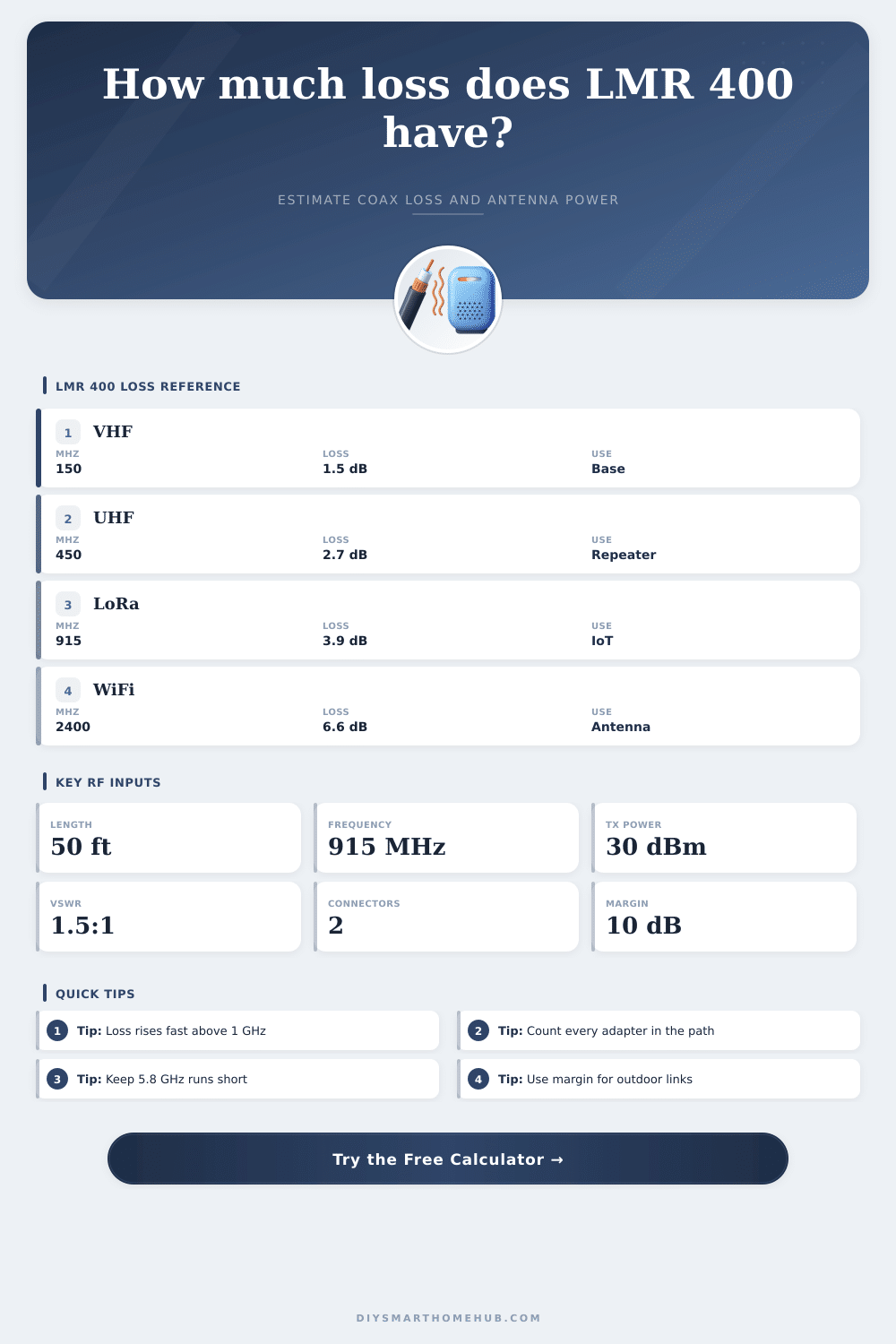
| 150 MHz | 1.5 dB | 4.9 dB | VHF base antennas and weather receivers. |
| 450 MHz | 2.7 dB | 8.9 dB | UHF, GMRS, and scanner antenna feeds. |
| 900 MHz | 3.9 dB | 12.8 dB | 915 MHz LoRa, ISM telemetry, and IoT gateways. |
| 1500 MHz | 5.0 dB | 16.4 dB | L-band receive systems and GNSS distribution. |
| 2400 MHz | 6.6 dB | 21.7 dB | 2.4 GHz WiFi or point-to-point antenna feeds. |
| 5800 MHz | 10.8 dB | 35.4 dB | 5.8 GHz bridge links where short coax is important. |
🔧Cable and spec comparison grid
| Cable type | 450 MHz loss | 2400 MHz loss | Planning note |
|---|---|---|---|
| LMR-400 standard | 2.7 dB / 100 ft | 6.6 dB / 100 ft | Baseline low-loss 400-series coax for fixed runs. |
| LMR-400-UF flexible | about 2.9 dB / 100 ft | about 7.1 dB / 100 ft | More flexible, usually a small loss penalty. |
| LMR-400-DB direct burial | about 2.7 dB / 100 ft | about 6.7 dB / 100 ft | Similar RF loss with outdoor jacket protection. |
| RG-213 class | about 4.1 dB / 100 ft | often 12+ dB / 100 ft | Usable at VHF, much lossier at WiFi frequencies. |
| LMR-240 class | about 4.4 dB / 100 ft | about 12.9 dB / 100 ft | Thinner and easier to route, but shorter practical runs. |
🔌Connector and inline loss reference
| Item | Typical loss | When to count it | Calculation impact |
|---|---|---|---|
| Quality N connector | 0.05 to 0.10 dB | Every feedline end and bulkhead. | Small individually, visible in low-margin links. |
| SMA or RP-SMA connector | 0.10 to 0.20 dB | WiFi, LoRa, LTE, and gateway pigtails. | Adds up quickly with adapters. |
| Barrel or right-angle adapter | 0.15 to 0.35 dB | Any extra mechanical conversion in the run. | Often avoidable by choosing the correct cable end. |
| Lightning arrestor | 0.20 to 0.60 dB | Outdoor mast or roof entry protection. | Enter as inline device loss. |
| Splitter or duplexer | 0.5 to 6+ dB | Shared antenna, repeater, or distribution paths. | Can dominate the cable loss budget. |
🏠Common project size examples
| Scenario | Frequency | Run length | Expected cable loss |
|---|---|---|---|
| LoRa gateway in attic | 915 MHz | 35 ft | About 1.4 dB before connectors. |
| VHF weather antenna | 162 MHz | 60 ft | About 0.9 dB before connectors. |
| UHF scanner mast | 450 MHz | 80 ft | About 2.2 dB before connectors. |
| 2.4 GHz WiFi antenna | 2400 MHz | 20 ft | About 1.3 dB before connectors. |
| 5.8 GHz bridge pigtail | 5800 MHz | 25 ft | About 2.7 dB before connectors. |
💡Coax loss planning tips
Feed the cable into the house through the wall and mount your antenna on the roof. Flip the switch. Power is lost as coaxial cable absorbs it along its length. Cell boosters, LoRa gateways, and ham operators commonly use LMR-400 for their runs because it offers both low loss and flexibility. But that doesn’t mean laws of physics don’t apply to coax either.
The feed line calculator figure out the numbers for you. But knowing what they mean will prevent you from making feedline buying mistakes before you buy the feedline. Finally, lower frequencies fade less severely. For instance, if you are pulling off 50′ of LMR-400 for a VHF weather antenna @ 150 MHz, the loss will be negligible. But if you attempt to do that with the same run at 2.4 GHz (WiFi) or 5.8 GHz (a wireless bridge), you’ll drop half your power. As frequency goes up, loss becomes very severe.
Why Signal Strength Drops in Cables
That’s why instead of just asking for “what standard” frequency, the tool requests what you’re actualy planning on using. A small change in MHz can make all the difference in the world between static and a good link. The calculator does the interpolation for you, eliminating the need to flip through manufacturers’ charts.
Connectors cause loss. This brings us to connectors. We frequently talk about how long a cable should be but forget about fittings used at each end. Each bulkhead fitting, SMA adapter or N-type connector contribute to the loss. While each one has a small effect on its own, stacking five adapters on high-frequency feed causes a large loss. This tool will allow you to list out the connectors and visualize the impact. No amount of additional transmit power will save you if a poorly connected adapter is in place; it simply warms the coax rather than improving the signal.
This also includes VSWR, which is far more important then most hams know. When the impedance of your antenna doesn’t match the impedance of the feedline, some energy reflect back towards the source. That reflected energy isn’t lost, it combines with forward signal to create standing waves which result in increased loss (effective loss) and heat. The tool will take the mismatch loss into account, which is critical if you’re using makeshift dipoles or other generic antennas. While a 1:1 VSWR is theoretically perfect, it’s often OK in practice to have up to 1.5:1, still costing you something. By knowing precisely how much you are paying for that, you can determine if you should of gone out and spend money on a better antenna, or roll with the loss as part of design of the system.
Percentage delivered lets you get a feel for how efficient you are. When it says 60 percent, you realize that two-fifths of your signal has been lost in wire alone. This is not necessarily bad if it’s a short run, but it is very important when you’re pushing your signal out as far as you can go, all the way to the edge of receiver’s sensitivity range. Finally, the link margin pulls everything together by measuring your EIRP at the end compared to receiver threshold and distance. If your margins is tight, a single loose connector or a rain storm can kill connection.
Remember, there are physical limitations with LMR-400 as well. While it’s thinner than RG-58 and will work for most home installations, it also won’t fit through a typical cable hole. If this bothers you, consider buying a direct burial version (it doesn’t affect RF very much, just adds some jacket protection for outdoor runs close to your house). There are several variants; pick one to match how many bends you’ll be making in an attic or around a corner.
Coax planning is all about managing expectations. Hope doesn’t beat the laws of attenuation. Clean up your connector count, reduce frequency wherever possible, and minimize length to minimize it. Plug your scenario into the calculator at the top of this page and let the math do the work so you don’t have to guess the numbers. It is your job to understand why a 3 dB loss cuts the range in half. Respect the signal path from radio to air. Don’t forget it pays the invisible tax too, no matter how much you paid for the cable. Measure twice, connect once.