Cat6 Cable Diameter Calculator
Estimate individual Cat6 outside diameter, bundle diameter, conduit fill, bend clearance, and tray capacity from cable construction and pathway limits.
Cable outside diameter
6.0 mm
Bundle diameter
33 mm
Conduit fill used
258%
Bend space
24 mm
| Cable type | Typical OD | Shield factor | Diameter note |
|---|---|---|---|
| Slim Cat6 UTP patch | 3.8-4.5 mm / 0.150-0.177 in | 1.00x | Small patch leads; verify channel limits and PoE heating. |
| Standard Cat6 UTP | 5.8-6.3 mm / 0.228-0.248 in | 1.00x | Common home and office horizontal cable size. |
| Cat6 CMR riser UTP | 6.0-6.6 mm / 0.236-0.260 in | 1.01x | Riser jackets can be slightly thicker than patch cable. |
| Cat6 CMP plenum UTP | 5.7-6.4 mm / 0.224-0.252 in | 1.02x | Plenum compounds vary; use the maker datasheet where available. |
| Cat6 F/UTP foil shield | 6.3-7.0 mm / 0.248-0.276 in | 1.05x | Overall foil adds diameter and usually raises bend radius. |
| Cat6 U/FTP pair shield | 6.5-7.2 mm / 0.256-0.283 in | 1.08x | Pair foils add stiffness even when OD looks modest. |
| Cat6 S/FTP braid and foil | 7.0-7.8 mm / 0.276-0.307 in | 1.12x | Braid and foil need larger pathways and sweeping bends. |
| Outdoor Cat6 CMX | 6.8-8.2 mm / 0.268-0.323 in | 1.10x | UV or water-blocking jackets are thicker and less flexible. |
The calculator can use these typical values or a direct measured OD override from the cable jacket or datasheet.
| Pathway | Inside diameter | 40% fill area | Approx Cat6 UTP count |
|---|---|---|---|
| 1/2 in EMT | 15.8 mm / 0.622 in | 78 mm² / 0.121 in² | 2 cables at 6.0 mm OD |
| 3/4 in EMT | 20.9 mm / 0.824 in | 137 mm² / 0.213 in² | 4 cables at 6.0 mm OD |
| 1 in EMT | 26.6 mm / 1.047 in | 222 mm² / 0.344 in² | 7 cables at 6.0 mm OD |
| 1-1/4 in EMT | 35.1 mm / 1.380 in | 387 mm² / 0.600 in² | 12 cables at 6.0 mm OD |
| 1-1/2 in EMT | 40.9 mm / 1.610 in | 526 mm² / 0.815 in² | 18 cables at 6.0 mm OD |
| 2 in EMT | 52.5 mm / 2.067 in | 866 mm² / 1.342 in² | 30 cables at 6.0 mm OD |
Cable quantities are planning estimates. Pull tension, cable listing, local code, and manufacturer fill tables can require more space.
| Bundle count | 6.0 mm UTP bundle | 7.0 mm shielded bundle | Opening suggestion |
|---|---|---|---|
| 4 cables | 13 mm / 0.51 in | 16 mm / 0.63 in | Use at least a 20 mm clear path. |
| 12 cables | 23 mm / 0.91 in | 27 mm / 1.06 in | Use a 35 mm or larger sleeve. |
| 24 cables | 33 mm / 1.30 in | 38 mm / 1.50 in | Use a 50 mm opening or tray route. |
| 48 cables | 47 mm / 1.85 in | 54 mm / 2.13 in | Split bundles for easier pulling. |
| 96 cables | 66 mm / 2.60 in | 77 mm / 3.03 in | Use tray or multiple sleeves. |
Bundle diameter uses OD x square root of cable count x a looseness factor, so dressing method changes the final size.
| Project | Cables | Likely OD | Pathway note |
|---|---|---|---|
| Desk or media wall | 4-6 | 6.0 mm / 0.236 in | Small sleeve works if connectors are installed later. |
| Small office zone | 10-16 | 6.0-6.5 mm / 0.236-0.256 in | Often exceeds 3/4 in conduit fill when bundled. |
| Rack patch bundle | 24-48 | 4.2-6.0 mm / 0.165-0.236 in | Slim patch cable helps cable manager density. |
| Camera home run group | 16-48 | 6.2-7.4 mm / 0.244-0.291 in | Outdoor or shielded jackets need larger bends. |
| Tray backbone bundle | 48-120 | 6.0-7.0 mm / 0.236-0.276 in | Tray capacity should leave expansion space. |
A network cable looks like a skinny string. Stuff it behind your walls and move on.
Nope. Cat6 comes in various thicknesses, which determine if its connector will fit into a switch port, if the cable can be pulled tight without snapping, and how many can be stuffed into a conduit. Seems trivial…until you’re on a ladder with 40 stiff cables refusing to go down a narrow hole. Then you wish you had measured twice.
Why Cable Thickness Matters for Your Install
After entering the jacket type (and cable count), the calculator do the rest. It’s a lot easier than wondering if that bundle will physicaly fit in your conduit. There are no “one size fits all” Cat6 cable here. The patch cord behind your monitor might be barely half the thickness of the heavy duty outdoor cabling running through your attic. Selecting the right construction, such as standard UTP versus F/UTP, let the tool distinguish between them.
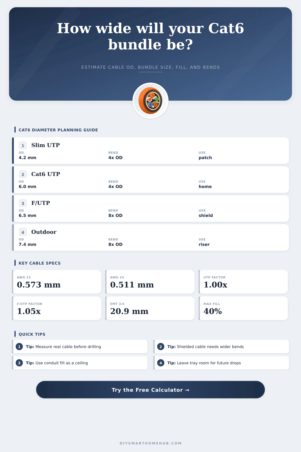
Adding shielding increases both the diameter and stiffness of the cable, which directly affects the maximum bend radius before signal degradation occur. You definitely want to know this before ordering conduit runs or drilling holes in your drywall. Many DIY installs go wrong because of the bend radius. There’s a point of curvature a cable will withstand before it shifts its insides and starts losing packets due to signal loss or crosstalk. Unshielded are generally 4x the diameter; shields usually need 8x. Do this wrong, and the cable work great initially and then loses packets three months from now as insulation settles. This chart on the page spells it out nicely for popular cable types. You’ll find yourself thinking that shielded runs requires a lot more space in those junction boxes.
Conduit fill is another consideration. Network best practices and electrical codes typically limit fill to no more than 40% for multiple cables. Why? It lets you pull new cables without pulling out existing ones, and it prevents heat from building up when too many cable are packed together. The calculator takes this into account when calculating your bundle’s diameter. It knows cables is round and they don’t pack tightly into a perfect circle.
Lacing neatly makes a tidy package that will lie flat in a tray. Velcro-wrapping messily means it gets fatter and harder to shove around corners. Choose the right looseness factor so you don’t buy conduit that seems big enough on paper but is actualy impossible to get anything through. The same reasoning applies to tray capacity planning, only at a bigger scale.
When routing cables through a ceiling tray or open rack, you’ll want to know whether there’s still space for additional drops when adding new equipment. A full tray becomes a solid block of plastic that prevents airflow, heats up, and renders trouble-shooting a nightmare. By entering the tray dimensions, the tool can calculate remaining free space from your first installation. It is better to have some unused space than to having to re-route the entire network because you suddenly need to add one more port down the hall.
The diameter is also an important thing to choose correctly, though the difference is subtle. For example, permanent runs should of use 23 AWG solid copper wire, which provides sufficient stiffness/pull strength. While 24 AWG may be ever-so-slightly thinner, it isn’t as strong for long horizontal pulls. If you don’t enter a custom diameter, the calculator will account for conductor size in its total diameter estimate. But keep in mind that each manufacturer handles jackets different. Just because two cables are in the same category doesn’t mean they’ll both have the same jacket thickness, because the amount of material used can change. That’s why we find it best to enter an outside diameter based off what you’ve actualy measured from your spool instead of just trusting generic defaults.
The physical world has become digital, and the digital world has become physical. Friction does not negotiate; neither does geometry. Drill first and then measure real cable to be sure your pathways allows for the actual hardware you’re going to install. Space constraints force reality on the numbers, which dictate the decision. Respect the fill limits, plan the bends now, and your installation will outlast the cables inside of it.