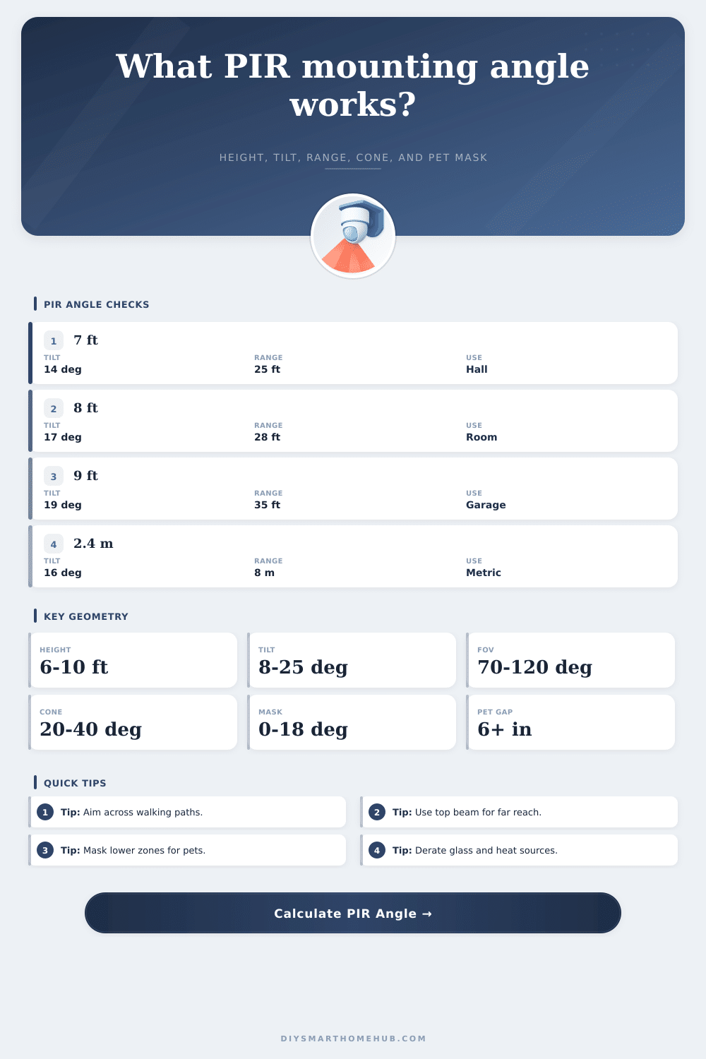
PIR Sensor Mounting Angle Calculator
Estimate the downward tilt, projected floor reach, cone width, mounting height effect, and lower pet-mask clearance for a PIR motion sensor before placing it on a wall, corner, or ceiling bracket.
Preset layoutsPick a sensor placement, then fine-tune the geometry.
Mounting inputsUse the sensor datasheet values when available.
Formula snapshot
The recommended tilt sets the upper active beam on the far floor point, then checks rated range projection and lower masked beam clearance.
PIR mounting result
Selected lens specsThese values update from the PIR profile dropdown.
Mounting angle referenceTypical indoor PIR geometry starting points.
| Mounting case | Typical height | Common tilt | Planning note |
|---|---|---|---|
| Standard wall PIR | 6.5-8.5 ft (2.0-2.6 m) | 10-20 deg | Best when people cross zones rather than walking straight toward the lens. |
| Long hallway | 7-9 ft (2.1-2.7 m) | 8-15 deg | Keep the upper beam near the far end so close floor coverage is not the only active area. |
| Pet-immune wall PIR | 7-8 ft (2.1-2.4 m) | 12-20 deg | Use lower mask clearance and avoid aiming directly at pet climbing surfaces. |
| Garage or utility zone | 8-10 ft (2.4-3.0 m) | 15-25 deg | Higher mounting needs a steeper tilt and usually a range derate. |
| Ceiling PIR | 8-12 ft (2.4-3.7 m) | Vertical pattern | Use diameter coverage from the datasheet; bracket tilt matters less than lens height. |
PIR lens comparisonUse profile type to decide what geometry matters most.
Wide room lens
Large horizontal FOV gives broad room coverage, but the far edge is usually range-limited before it is width-limited.
Long-range lens
Narrower field angle concentrates zones down a hall or aisle. Height and tilt changes affect the far beam noticeably.
Curtain lens
Small horizontal width creates a detection plane. It works well across doors, windows, and boundary lines.
Pet-immune lens
Lower zones are masked or reduced. The important number is clearance above pet shoulder height at normal pet paths.
Ceiling PIR
Coverage is usually a floor circle or oval under the lens. Mounting height mostly changes diameter and blind spots.
Outdoor PIR
Use a stronger derate because sun, wind, reflected heat, and approach direction can reduce useful detection range.
Coverage tableReference values for range projection and cone width.
| Sensor profile | Horizontal FOV | Vertical cone | Typical range |
|---|---|---|---|
| Wide wall PIR | 100-120 deg | 25-35 deg | 25-40 ft (7.6-12.2 m) |
| Long-range PIR | 20-60 deg | 15-30 deg | 40-80 ft (12.2-24.4 m) |
| Curtain PIR | 5-20 deg | 60-90 deg | 15-35 ft (4.6-10.7 m) |
| Pet-immune PIR | 80-110 deg | 20-35 deg | 25-35 ft (7.6-10.7 m) |
| Ceiling PIR | 360 deg pattern | 70-100 deg | 12-30 ft diameter (3.7-9.1 m) |
Common placement checksUse these as sanity checks after calculating.
| Placement | Input to watch | Good signal | Adjustment |
|---|---|---|---|
| Corner room sensor | Cone width | Width covers primary walking path | Reduce tilt if the far wall is missed. |
| Entry wall sensor | Near floor intercept | Door swing is inside active zone | Use less lower mask if the entry zone is too high. |
| Pet-safe room | Pet-mask clearance | 6 in (15 cm) or more over pet height | Raise lower mask or increase mount height. |
| Hallway sensor | Projected reach | Derated reach clears far point | Use long-range lens if reach is short. |
| Garage PIR | Mount height and derate | Tilt stays under 25 deg | Lower the sensor or choose a wider vertical cone. |
Calculation notesGeometry assumptions used in this tool.
| Formula | What it estimates | Inputs used | Limit |
|---|---|---|---|
| atan(height / far) | Upper beam downward angle | Mount height, desired far point | Flat-floor approximation |
| upper angle + vertical half cone | Recommended center tilt | Mount height, far point, vertical cone | Datasheet beam patterns vary |
| rated range x cos(tilt) x derate | Horizontal floor reach | Rated range, tilt, derate | Heat contrast changes real reach |
| 2 x distance x tan(FOV / 2) | Cone width at distance | Horizontal FOV, reach | Uses ideal sector geometry |
| height - distance x tan(lower angle) | Lower active beam height | Tilt, cone, mask, pet path | Pet movement and furniture matter |
There is a motion sensor. Maybe you leave the lights on and set them on an automatic timer, but then notice they turns on even though no one’s home. Why? Because you didn’t read the manual before automating something! The issue isn’t with the technology; it’s typicaly about how you install the thing.
A passive infrared sensor do not register light and dark. It registers changes in amount of heat within certain zones made by a Fresnel lens. Those zones is determined by the sensor’s tilt angle and its mounting height. If the ceiling angle are too steep, you get a detection desert out on the floor. Too little, you lose the temperature contrast of somebody close to wall. The calculator above do that for you. Knowing why all those numbers has meaning will save you some frustration down the road.
How to Install Motion Sensors Correctly
Naturaly most folks think that high mounting is good because it provides a broader vantage point. For wall mounted sensors, that’s mostly incorrect. If you elevate the sensor (for example, from 7 ft. Up to 9 ft.), you have to shoot at a much steeper angle in order to scan the back of the room. It stretches the vertical coverage too thinly over the span.
To compute this, we apply simple trigonometry: the arctangent of the mount height (divided by) how far you want the range to go. Then we adds half the vertical cone diameter to ensure the top of the active beam reaches the exact spot on the floor you need. This avoids a common error of pointing dead-center in the room and thereby failing to cover the doorway at all.
Of all the inputs into motion planning, perhaps the one that gets overlooked most is the derate factor. Sensors are rated by manufacturers in lab settings where there’s a lot of thermal contrast and no heat sources like radiators or sunlight through windows. Furniture obstruct an line-of-sight. Real homes are messy places. A ten to thirty percent reduction to the rated range can account for these factors in the real world. Ten to thirty percent may sound crazy, but it’s a conservative estimate that prevents you from having dead zones at critical spots in your hallways. You shouldn’t of want the security system depending on theoretical maximums while a draft comes from an open door and washes out the infrared signature of an intruder.
There is another wrinkle in this geometry called pet immunity. To avoid false alarms from small pets scampering across the floor, these sensors uses a lower mask that blocks the bottom part of their field of view from infrared energy. The question then becomes whether the masked area remains above your dog’s typical walking path (above its shoulder), measured by a clearance calculation. If not, if the math reveals negative clearance. Then the lower active beam drop below your pet’s level and you’ll still get an alarm. Adjusting the mounting height or the angle of the mask are two fixes that will add a few inches of buffer space. That’s for when your pet runs or jumps, momentarily altering his or her profile compared to lens.
So before you even get to tilt, the type of lens determines the coverage area. Lenses narrows or widens what it sees, and each has its strengths and weaknesses. Wide angle lenses cover a large area but lose range. Long range lenses narrows the coverage area to a beam that stretches way down a corridor but must be aimed precisely. This table on the page show the tradeoffs between profile types, and how they either increase breadth by losing range or increase range by losing breadth. Using the wrong lens for an area is like attempting to illuminate a space with a telescope where a flashlight would of been better. While you can tilt somewhat, you cannot alter the basic nature of the optics in the device.
Even outdoors there’s more reason to be careful about things interfering with your setup: Trees sway in the breeze; hot pavement radiates upward; and direct sun create both blind spots and false positives. The calculator lets you apply a stronger reduction factor here as well, recognizing that nature can be a bit messy (to put it mildly) versus the orderly confines of an office hallway. In other words, it makes you design for the worst-case scenario, not the best.
Wiring aside, mounting a PIR sensor requires spatial awareness. You are placing a thermal eye in a three-dimensional space based off how people move. Drill holes knowing beforehand the angles from which your sensor will see. Make sure it’s looking at what you want it to see and not at what you don’t. Translate guesswork into geometry. Have faith your system will do its thing when you really need it to. It is not merely motion detection, but motion detection at the right time for the right kind of motion.