IDMT Relay Trip Time Calculator
Calculate IEC 60255 inverse-time overcurrent relay operation from CT ratio, relay pickup, primary fault current, time multiplier setting, reset margin, instantaneous pickup, and breaker clearing allowance.
📌Named relay setting presets
⚙Relay and fault inputs
IEC inverse trip estimate
Enter relay settings and calculate to see pickup multiple, IDMT time, instantaneous status, and total clearing allowance.
🔌Live setting grid
📊Relay curve comparison grid
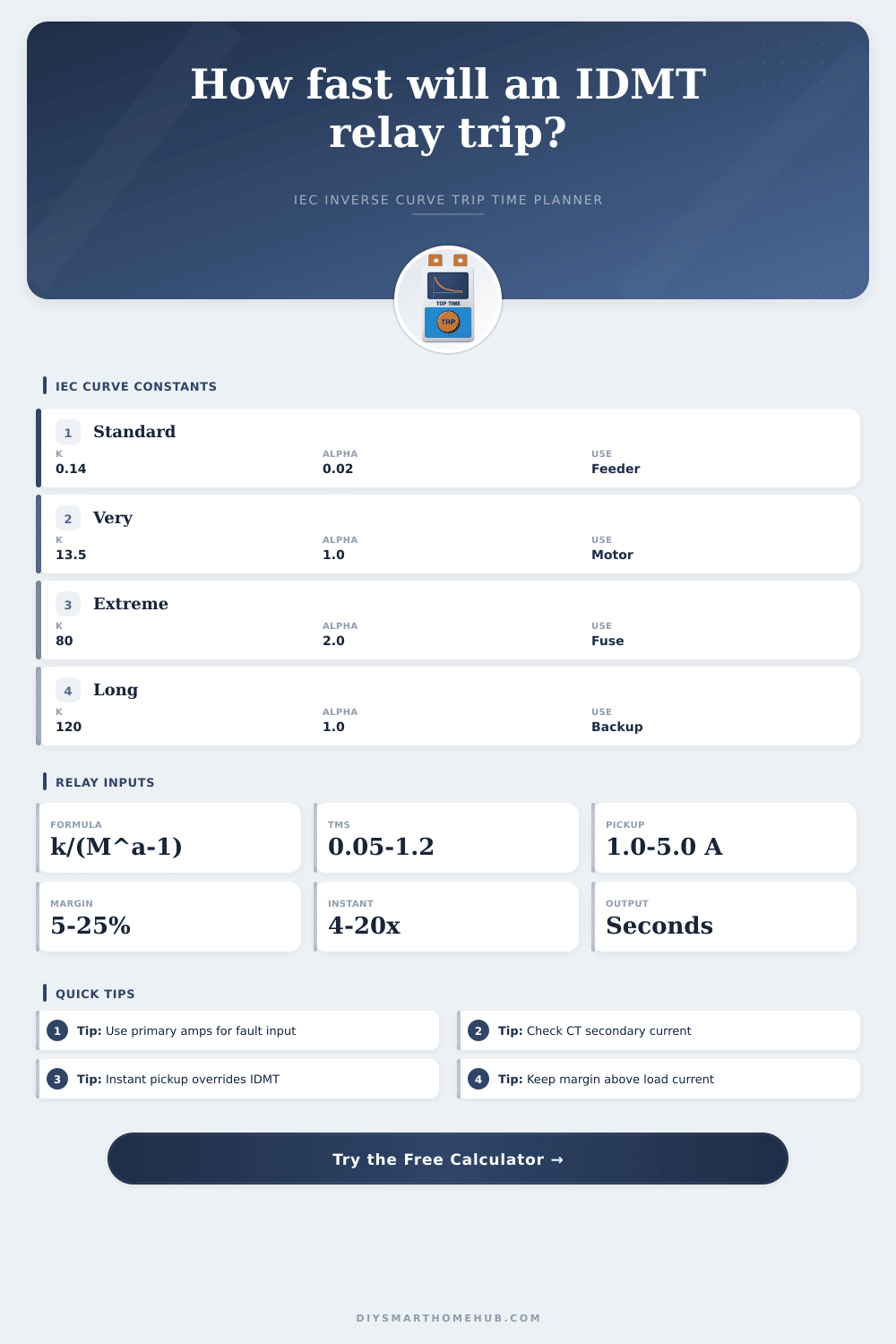
| IEC curve | Equation constants | Relative shape | Typical coordination role |
|---|---|---|---|
| Standard Inverse | k 0.14, alpha 0.02 | Moderate inverse slope | General feeder backup, utility incomers, broad grading steps |
| Very Inverse | k 13.5, alpha 1.0 | Steeper at higher fault multiples | Motor feeders, downstream device grading, medium-voltage feeders |
| Extremely Inverse | k 80, alpha 2.0 | Very steep high-current operation | Fuse coordination, transformer secondary faults, cable protection checks |
| Long-Time Inverse | k 120, alpha 1.0 | Longer time delay for backup | Remote backup, long feeders, intentional upstream delay |
📛IEC 60255 formula reference
| Item | Symbol | Calculator expression | Planning note |
|---|---|---|---|
| Pickup multiple | M | Fault current / primary pickup | Inverse timing begins only when M is above the margin-adjusted pickup point. |
| IEC trip time | t | TMS x k / (M^alpha - 1) | Time is in seconds before breaker clearing allowance. |
| Primary pickup | I> | Relay secondary pickup x CT primary / CT secondary | Use actual CT ratio and relay tap or digital setting. |
| Instantaneous trip | I>> | Primary pickup x threshold multiple | When enabled and exceeded, instant delay replaces IDMT time in this estimate. |
📏Pickup multiple timing examples at TMS 0.10
| Multiple of pickup | Standard inverse | Very inverse | Extremely inverse | Long-time inverse |
|---|---|---|---|---|
| 2 x pickup | 1.00 s | 1.35 s | 2.67 s | 12.00 s |
| 5 x pickup | 0.43 s | 0.34 s | 0.33 s | 3.00 s |
| 10 x pickup | 0.30 s | 0.15 s | 0.08 s | 1.33 s |
| 20 x pickup | 0.23 s | 0.07 s | 0.02 s | 0.63 s |
🛡Application reference table
| Application | Common curve | Common TMS range | Setting checkpoint |
|---|---|---|---|
| LV feeder backup | Standard inverse | 0.10 to 0.35 | Pickup should exceed expected load and motor starting current. |
| Motor control center | Very inverse | 0.08 to 0.25 | Coordinate with motor overload and short-circuit device curves. |
| Transformer feeder | Standard or extremely inverse | 0.15 to 0.50 | Check inrush restraint, downstream breaker, and through-fault duty. |
| Earth fault element | Standard inverse | 0.05 to 0.25 | Use residual CT data and neutral grounding limits where applicable. |
| Long cable feeder | Long-time inverse | 0.20 to 0.80 | Minimum remote fault must still exceed margin-adjusted pickup. |
| Fuse coordination | Extremely inverse | 0.05 to 0.20 | Compare against fuse melting and clearing curves at the same current. |
💡Calculation tips
When there’s a fault, the circuit breaker will stay closed for specific amount of time required by the relay. That duration is vital as the device nearest to the issue will be the one that clears the fault first. The next device upstream will pause for its turn and won’t trip unnecessarily. In this way, only faulty section is isolated and healthy parts of network continue running. It’s all about timing; not just current limits, that protects the system. International standards (IEC 60255) define the mathematics for these times.
You do not need to memorize the formula as much as understand what it means given specific inputs into physical system. First look at your current transformer ratio. This can be easily messed up when rushing through a study and is one place where settings tends to get knocked out of whack over time. If your CT is a four-hundred amp primary to five-amp secondary, and you choose two point five-amps for your relay pickup at the secondary, you’ve actualy protected two hundred-amps on the line side. The primary equivalent should always be double checked because a single decimal point error will move your whole coordination curve by orders of magnitude.
How to Set Up Circuit Breaker Protection
For your second step, you’ll want to match the inverse curve type to the piece of equipment it’s protecting. Generally speaking, most utility connections and other types of more generic feeders responds well to a standard inverse curve. It has a bit of a slope that provides some selectivity while not taking too long to open at higher fault levels. If you have long cable runs or are feeding something like a motor, then you should of consider a steeper curve like Extremely Inverse or Very Inverse. These will be quicker to trip at higher levels of fault but take longer to clear smaller overloads. That’s why it’s important to use this curve when trying to ride through momentary in-rush currents without tripping unnecessarily.
Below is a chart that shows the impact of varying curve constants and their effect on opening time for different multiple level of current. You can adjust the time multiplier setting to scale the whole curve up or down. It is linear, so you are stretching or compressing trip times but not altering the shape of the curve. The purpose of the setting is to establish a grading margin between your devices. Typically you want to set this at about 30 milliseconds, allowing enough time for the lower breaker to clear before the upper one starts its work. If you reduce this interval too much, relay jitter and mechanical delays could cause both breakers to open together. This is worst case for maintenance crews attempting to isolate the issue.
Remember that part about the instantaneous? If you understand inverse curves, you know they handle moderate short circuits and overloads, whereas bolted faults close to the source require an immediate response. That is where the instant pickup comes into play. If set above the curve, it ignores the time delay for any value higher than the instant pick up. It will override the curve rules and shut off the fault in milliseconds protecting against dangerous faults. Once triggered it will totally override the IDMT calculation. You don’t want to go too low or it will trip on start motors but you don’t want to go to high because it will allow your cable to be thermally damaged.
Clean equations ignore real-world elements. Transient inrush currents occur. Harmonic distortion is present. CTs saturate. In reality, they matter. The calculator gives you a starting place and testing in the field confirms it. Be careful with the reset margin setting too. Without it, if your load varies around the pickup point, the relay may chatter on and off. Ten-percent headroom keeps operation steady against small disturbances.
So how does it work? It’s all about how the protections works together; you have to trust not only the hardware but also the math behind what you are doing. Whatever you input as an entry will translate exactly into the action of your switchgear. You want the breakers to trip quickly but selectively. If it trips fast when it’s supposed to, then the sound of the breaker snapping means it is dependable; if not, then it means it failed.