Hysteresis Threshold Calculator
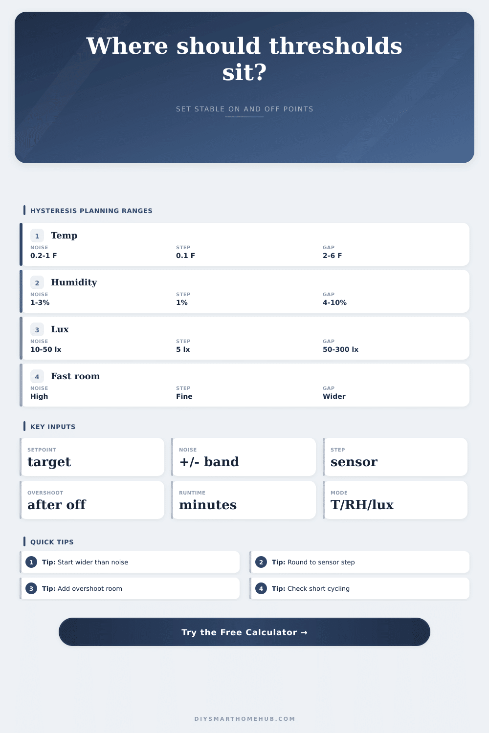
Calculate stable upper and lower smart home trigger thresholds from the target setpoint, sensor noise band, measurement resolution, overshoot, minimum runtime, and temperature, humidity, or lux mode.
Recommended hysteresis thresholds
| Control type | Common gap | Resolution | Use when |
|---|---|---|---|
| Room temperature | 2-6 °F | 0.1-1 °F | HVAC or fans |
| Water temperature | 0.5-2 °F | 0.1 °F | Aquarium heat |
| Relative humidity | 4-10% | 1% | Fans or drying |
| Indoor lux | 50-300 lx | 5-25 lx | Lights or shades |
| Outdoor lux | 200-1000 lx | 25-100 lx | Daylight gates |
| Step | Formula | Purpose | Output |
|---|---|---|---|
| Noise guard | 2 x noise + step | Avoid chatter | gap need |
| Resolution guard | 2 x step | Separate readings | gap need |
| Overshoot guard | 2 x overshoot + noise | Allow coast | gap need |
| Runtime guard | minutes x rate | Limit cycling | gap need |
| Final gap | max guards, rounded | Sensor-ready | deadband |
| Action | Turn on at | Turn off at | Example |
|---|---|---|---|
| High reading | Upper threshold | Lower threshold | Cooling |
| High reading | Upper threshold | Lower threshold | Dehumidify |
| High reading | Upper threshold | Lower threshold | Close shades |
| Low reading | Lower threshold | Upper threshold | Heating |
| Low reading | Lower threshold | Upper threshold | Add light |
| Scenario | Mode | Target | Typical gap |
|---|---|---|---|
| Bedroom cooling | Temp | 74 °F | 3-5 °F |
| Bathroom fan | Humidity | 60% | 6-10% |
| Grow light assist | Lux | 450 lx | 80-160 lx |
| Aquarium heater | Temp | 78 °F | 1-2 °F |
| Server closet fan | Temp | 82 °F | 4-8 °F |
So it’ll turn the heater on and off, say, every four seconds, causing a rapid cycle where the equipment will wear itself out and waste energy. But it’s not because your equipement is broken; it’s not because one of the sensors are bad. It’s because there’s a gap in the logic. You call that gap hysteresis, and in a climate control loop, it is single most important setting to have. Without it, the system chases its own tail. With it, the room settles into a stable rhythm.
If you set your heat to be seventy-two degrees, you should understand when it stops. When the sensor reaches that point, the heater shuts off. But that doesn’t mean the room immediately stop changing. There’s still lingering heat. And the sensor bounces around. It goes down to seventy-one-point-nine. The heater powers back on. The process continues forever. What you want here is what we call a deadband: a range within which the system remains idle. Only once the environment has stabilized will the system take another action. Without this buffer, you get the kind of jittery action that hurts so much DIY automation.
Why You Need a Buffer in Your Controls
First, how much of a buffer should you set? That depends off sensor noise. No digital sensor is absolutely motionless. It will bounce up and down (say, a percentage point of humidity or a fraction of a degree), even in a still room. If your gap is narrower than its natural wandering, the controller will react to static rather then actual change. Think about drawing a straight line with a quivering hand. You need to set the gap larger than amount of wobble in the sensor. When you do, random fluctuations won’t call for needless commands.
There’s also overshoot (another physical reality). When your heater or fan goes off, the temperature doesn’t freeze in place. It continues to coast. Even if there is still some leftover airflow in a server closet, it could of take a minute for that fan to shut off. This continues to drop the temperature. The system turns off and the room continue to cool. Once the threshold is crossed, the fan turns back on. You’re fighting physics. To account for this coasting effect, you add additional room in the gap. Recognize that the surroundings has momentum.
On the practical side, runtime matters. Short bursts don’t play well with mechanical devices. It takes some time for a high-wattage heater or a compressor to operate at best efficiency and not put itself through thermal stress. If you set your thresholds so closely that the system reaches those thresholds within thirty seconds, then you’re short-cycling the equipment. That lowers efficiency and lifespan. A greater distance gives the device enough time to be actualy working and allows the device to rest once it’s finished its task.
This puts all those variables together, then produces a solid set of triggers. These take into account both the likely amount of sensor noise, as well as the physical overshoot and resolution of the sensor itself. The result is a safe operating zone. Half of the battle is numbers. The other half is observation. Get to know your environment.
When you don’t have anything moving, watch the sensor. Notice how far it bounces around? That is your noise band. Round your trigger points to align with the sensors step size. Seventy-two-point-three-five degrees isn’t worth much if the sensor can only report whole numbers. The same applies to lighting and humidity, though with different numbers: A lux sensor is jittery (it responds to dust motes, passing cars and clouds) and need much wider gaps than temperature sensors to avoid flickering lights. Humidity fluctuates slowly but steadily. Often it takes longer runs to detect any change at all. The reference table breaks down normal ranges in each of those operating modes. That gives you a starting place to tweak the settings.
A well-automated system is one where you don’t even know it’s automated. You’re not aware of the fan cycling on and off. You never see the lights going up and down in abrupt little steps. Instead you’re just comfortabley. Nature behaves this way; so does good tech, thanks to hysteresis. There are no jarring leaps and bounds. It moves in gentle slopes and steady plateaus. Set the gap correctly and the room finds its happy place. Set it incorrectly and you leave your nervous system unable to stop twitching. Give it some breathing room.