Mesh Repeater Placement Spacing Calculator
Estimate Zigbee, Thread, Z-Wave, and Wi-Fi mesh repeater spacing from room size, open-room radius, wall attenuation, overlap, hop count, and coverage area.
Formula breakdown
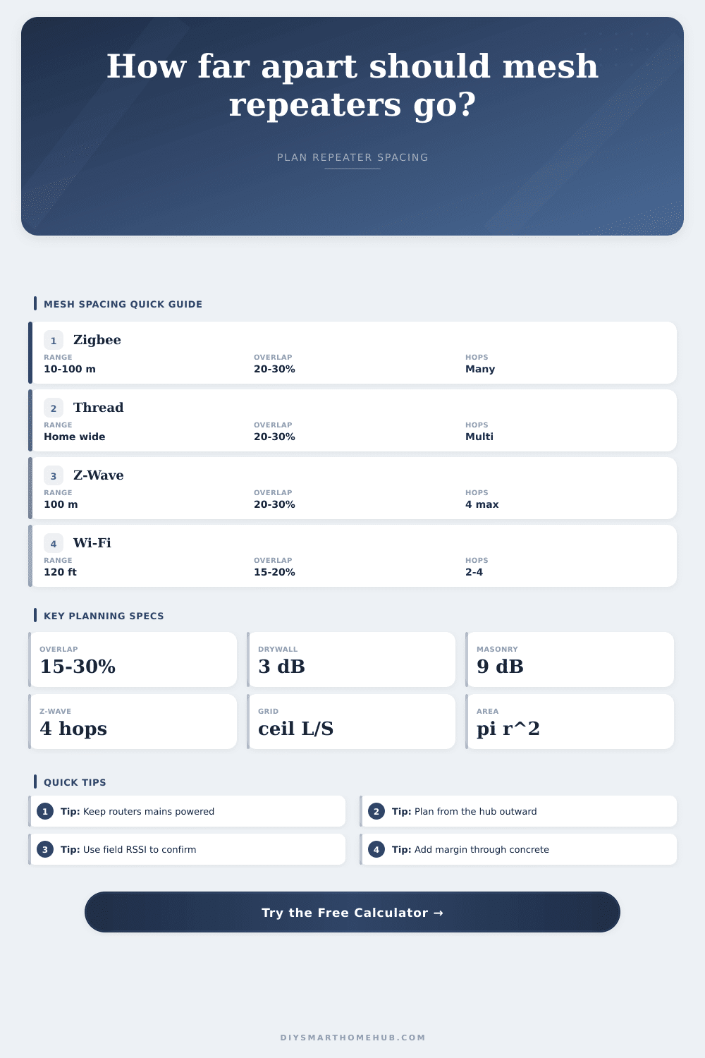
| Protocol | Verified planning fact | Calculator default | Overlap target | Hop planning note |
|---|---|---|---|---|
| Zigbee | CSA lists 10 to 100 m transmission distance depending on environment | 33 ft / 10 m indoor radius | 25% | Use mains-powered routers; battery end devices do not relay |
| Thread | Thread is a self-healing low-power mesh for home-scale coverage | 40 ft / 12 m indoor radius | 25% | Router-capable Thread devices extend the mesh from border routers |
| Z-Wave | Z-Wave Alliance lists 100 m per hop for classic Z-Wave line-of-sight | 80 ft / 24 m indoor radius | 25% | Plan against the classic 4-hop route limit |
| Wi-Fi mesh | Cisco notes AP separation often depends on RF objects and overlap needs | 60 ft / 18 m indoor radius | 20% | Keep wireless backhaul hops low, usually 1 to 2 when possible |
| Obstacle model | Loss used | Material examples | Distance effect | When to raise the count |
|---|---|---|---|---|
| Open air | 0 dB | Same room, direct hallway, clear landing | 100% of open-room radius | Only if interference is high |
| Light wall | 3 dB each | Drywall, plasterboard, wood, ordinary glass | Small to moderate reduction | More than two walls per link |
| Heavy wall | 9 dB each | Brick, concrete, tile, metal door, foil insulation | Large reduction | Any concrete, metal, or masonry path |
| Sub-GHz adjustment | 0.75x wall loss | Z-Wave style lower-frequency path | Better penetration model than 2.4 GHz | Still add nodes near metal or concrete |
| Wi-Fi adjustment | 1.15x wall loss | Higher-band mesh backhaul through rooms | More sensitive to walls | When 5 GHz or 6 GHz backhaul is weak |
| Spacing goal | Formula | Example with 40 ft radius | Planning meaning | Best use |
|---|---|---|---|---|
| Light overlap | radius x (1 - 0.15) | 34 ft spacing | Minimal overlap, faster count estimate | Open Wi-Fi data coverage |
| Balanced overlap | radius x (1 - 0.25) | 30 ft spacing | Good margin between adjacent mesh nodes | Zigbee, Thread, Z-Wave homes |
| Conservative overlap | radius x (1 - 0.35) | 26 ft spacing | More nodes, shorter links, better redundancy | Thick walls or dense devices |
| Coverage area | pi x radius squared | 5,027 sq ft before packing | Upper-bound circle area, reduced by layout factor | Sanity-checking node count |
| Grid count | ceil(length / spacing) x ceil(width / spacing) | 3 x 2 = 6 nodes | Rectangular placement estimate | Repeater layout sketching |
| Scenario | Protocol | Modeled size | Wall path | Suggested starting layout |
|---|---|---|---|---|
| Small apartment | Wi-Fi or Thread | 30 x 22 ft | 0 to 1 light wall | Hub plus one central node if back rooms test weak |
| Sensor-heavy apartment | Zigbee | 55 x 32 ft | 2 light walls | Two to three mains routers spread through rooms |
| Long ranch home | Z-Wave | 105 x 42 ft | 2 light walls | Outlet repeaters every 45 to 60 ft along the run |
| Two-floor mesh | Wi-Fi mesh | 70 x 46 ft | 2 light, 1 heavy path | One wired or strong backhaul node per floor zone |
| Garage bridge | Zigbee or Z-Wave | 120 x 28 ft | 2 light, 1 heavy path | Place a mains repeater at each transition point |
Anyone who’s automated their house knows that they spends as much time troubleshooting why things don’t work as they do celebrating success. Usually its because the smart home tech doesn’t want to play nice with your space. It’s more about physics of radio waves and geometry of your walls than any flaw in the tech. Mesh networks aren’t magic either; while forgiving, they still needs carefully placed nodes for proper performance… Particularly if you’re juggling multiple protocol such as Wi-Fi, Thread, Zigbee and Z-Wave. They all vie for airtime on the same spectrum.
You type in your floor dimensions and wall types (the calculator above do all the math). This removes any guesswork as to how many nodes you really need. Most people greatly underestimate how much a single concrete wall reduce your signal. Drywall simply gets in the way of radio frequencies. Metal framing, masonry etc… it’s a vacuum cleaner for data packets.
How to Place Your Smart Home Nodes
Enter number of ‘heavy’ walls into the tool and consider fact that your home isn’t exactly an open field. Signals shrinks a lot as they hit denser materials. So, your best node spacing will get much closer together. Secondly, just because there’s a mesh node doesn’t mean it’s capable of helping route traffic. Most sensors that will connect to network; especially battery-powered ones. Don’t contribute anything to extending its reach. They’re dead ends. To actualy have things route through, you’ll need dedicated mesh nodes or routers that draws power from the grid. That means if your hub sits behind a thick fireplace, don’t expect a battery thermometer on the other side of the house to remain connected.
The tool use realistic assumptions to calculate path loss and then determines number of hops based off those results. It warns you that each extra wall introduce latency, as well as more places where it could fail. Most DIY installers cut corners by avoiding sufficient overlap in their coverage areas. For example, they might place nodes just far enough apart that they can barely touch each other at their edges. But what happens when one of those links temporary weakens because of interference? With 20 to 30 percent overlap, you’re covered; there’s an alternate path if something blocks a link or interferes with it. Better to have more nodes then be stuck with a spotty connection while eating dinner.
That’s why the calculator tweaks how much space you should of leave between nodes based on your desired amount of overlap. Then it presents a grid layout made for strength rather than minimal hardware cost. The limitations affects different protocols differently. For example, Wi-Fi mesh tends to perform well with higher-bandwidth uses, and is also more negatively affected by neighborhood interference. Sub-GHz options such as Z-Wave will travel through walls more effectively, but only allow a certain number of hops before signal is too degraded to reliably send control commands.
That knowledge alters where you position your equipment. With Wi-Fi, perhaps group those units closer together to get that increased bandwidth? Also, position Z-Wave repeaters at the right distances to maximize reach. Do this without using too many hops. Your home’s layout cannot be replaced by any calculator (though this one certainly offers a solid starting guess). Purchase sufficient hardware based on the numbers; deploy initial nodes. See how the signal strength reads out in your hub interface or app. Tweak accordingly.
You’ll know when your mesh is properly set up, it becomes so seamless that you almost don’t notice it at all … except for when it fails. And you won’t make that error without considering both distance between your devices and what stands between them.