Circuit Load Balance Calculator
Estimate 120/240 V split-phase panel balance from leg A and leg B loads, 240 V shared current, neutral imbalance, continuous-load planning, and panel capacity limits.
⚡Load Balance Presets
🔌Panel And Planning Inputs
📋New Or Adjustable Circuit Loads
Split-phase load balance estimate
Calculation breakdown
📊Split-Phase Spec Grid
📐Reference Tables
| Load type | Voltage entry | Leg current formula | Neutral effect |
|---|---|---|---|
| 120 V branch circuit on leg A | VA or W at 120 V | Leg A amps = adjusted VA / 120 | Adds to A-side neutral imbalance |
| 120 V branch circuit on leg B | VA or W at 120 V | Leg B amps = adjusted VA / 120 | Adds to B-side neutral imbalance |
| 240 V two-pole load | VA or W at line-to-line voltage | Both legs get adjusted VA / 240 | No neutral current for pure line-to-line load |
| 120/240 V mixed appliance | Enter 240 V motor/heat plus 120 V controls separately | 240 V portion is equal; 120 V portion belongs to one leg | Only the 120 V portion affects neutral imbalance |
| Panel rating | 80% planning amps | Equivalent VA at 120/240 V | Use in calculator |
|---|---|---|---|
| 60 A panel | 48 A per leg | 11,520 VA total split-phase | Small subpanel or apartment load planning |
| 100 A panel | 80 A per leg | 19,200 VA total split-phase | Older home or compact smart home panel |
| 125 A panel | 100 A per leg | 24,000 VA total split-phase | Moderate service or feeder limit check |
| 150 A panel | 120 A per leg | 28,800 VA total split-phase | Load additions with larger appliance circuits |
| 200 A panel | 160 A per leg | 38,400 VA total split-phase | Common whole-house planning baseline |
| Common load | Typical circuit | Calculator entry | Balance note |
|---|---|---|---|
| Lighting and general receptacles | 120 V single-pole | Use actual VA or circuit estimate on A or B | Good candidates to move when one leg is heavy |
| Microwave or countertop appliance | 120 V 20 A | 1200-1800 VA on one leg | Can create large neutral imbalance if clustered |
| Electric dryer or range heat | 240 V two-pole | Nameplate VA as 240 V split | Raises both legs equally for the 240 V portion |
| EV charging circuit | 240 V continuous | EVSE output amps x 240 x 125% | Counts on both legs and uses continuous planning |
| Network rack or smart home hub | 120 V continuous | Measured watts with 100% continuous portion | Small load, but usually always on |
| Comparison case | Best placement | What improves | What stays limited |
|---|---|---|---|
| Many 120 V circuits on one bus | Move selected circuits to the lighter leg | Leg balance and neutral imbalance | Total panel demand may stay the same |
| Large 240 V appliance added | Two-pole breaker spans both legs | Balanced leg addition | Heavier-leg capacity because both legs rise |
| Continuous smart home equipment | Place on lighter leg when possible | Always-on balance margin | Continuous 125% planning still applies |
| Mixed 120/240 appliance | Split entries by voltage portion | More accurate neutral and leg estimate | Nameplate data may need interpretation |
🔧Load Balance Tips
At some point in your life, I’m sure, you’ve gazed at a breaker wall and been filled with fear. There seems to be no pattern to the madness; one side is loaded down with kitchen circuits while the other has just a couple of lights on it. It doesn’t make sense, it looks bad and it could be dangerous.
Before you throw a switch, use a circuit load balance calculator to see what isn’t visible. Ignore the numbers and you’ll trip a breaker. Use this handy tool to do the math for you so you can turn amperage ratings into real use. It’s a simple matter of math with dire results.
How to Balance Your Electric Panel
In a typical North American home, your service enter your house as split-phase power. There are two hot legs and a neutral wire running through. Consider the panel to be a sort of see-saw. If one side of it gets much heavier than the other, the entire system suffer.
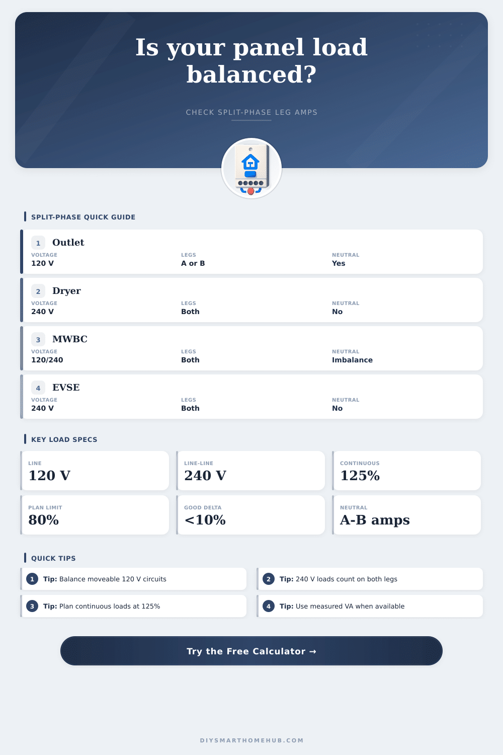
Electric dryers and water heaters is pure 240-volt loads. What does that mean? It means they pull current from both legs equally; they don’t throw off the balance of the system. As a result, adding a new 240-volt circuit isn’t likely to cause any trouble right away.
It’s the 120-volt circuits that becomes the problem. Why? Because these connect to either one leg or the other. If you group too many high-draw items on one leg (say Leg A), then you’re leaving Leg B sitting idle. When you do that, you’re pushing the main breaker closer to its limit.
Always watch your constant loads. This applies to anything that’s on longer than three hours. Electrical codes say you have to plan for them at 125 percent of what they actualy use, so this number is adjusted by the calculator. That way wires and breakers aren’t being constantly worked, which could lead to overheating if they’re never allowed to cool back down.
Without this adjustment, your numbers seem rosy. But in summertime when it gets hot, all those air conditioners could simultaneous turn on, and you know what? It happens. A tiny multiplier, but oh-so-important for long-term safety.
There’s also a hidden variable called neutral imbalance. The neutral wire represents the difference in current being pulled from both legs. If one leg (Leg A) pulls 15 amps while the other leg (Leg B) pull 5, that 10 amp differential goes back via the neutral. There’s no way to offset that imbalance by simply adding more 240-volt loads; they don’t go near the neutral.
Your solution is moving around moveable 120-volt circuits. Receptacle outlets and general lighting are your best friends here. They’re easy to reassign and have huge impacts on overall symmetry.
When it comes to how much can fit on each leg, most people is guessing, and the reference table spells it out for you. The more breathing room you have (e.g., a 200-amp panel vs. Having more breathing room, such as a 200-amp panel instead of a 100-amp, is better. Consider today’s needs, such as heat pumps and electric vehicle chargers. Compare the heavier leg to the planning limit printed on your panel. It will be 80 percent of the main rating. If that seems high, consider relocating some single-pole breakers to the lighter side.
This is time-consuming stuff. You do it one breaker at a time. What goes here? Guessing, guessing, guessing. Maybe the lamp in your living room and the microwave in the kitchen is on the same leg. And you made this spike that you hadn’t expected. This isn’t a perfect art form; it’s about margin. You don’t want such tight margins that you have to call an electrician to upgrade your panel when you want to add some future device.
When you look back over all those breakers, it makes that crazy wall of breakers come alive again. You stop guessing and start planning. It gets to plan.