LED Strip Max Run Length Calculator
Estimate the longest practical LED strip run from supply voltage, W/m, strip copper weight, allowable voltage drop, feed method, brightness, ambient derating, and current per channel.
Maximum LED Strip Run Result
| Strip Copper | Approx Pair Resistance | Best Fit | Run Effect |
|---|---|---|---|
| 1 oz narrow strip | 0.095 ohm/m | Low-current accent strips | Shortest runs; inject often. |
| 2 oz standard strip | 0.062 ohm/m | Common 12 V and 24 V tape | Balanced general planning value. |
| 2 oz wide strip | 0.040 ohm/m | High-current COB or RGBW tape | Better for longer single sections. |
| 3 oz pro strip | 0.028 ohm/m | Bright coves and pixel runs | Lower voltage sag at same current. |
| 4 oz heavy strip | 0.022 ohm/m | Dense pixels and premium tape | Longest copper-limited sections. |
| Feed Method | Drop Factor | Meaning | Best Fit |
|---|---|---|---|
| Single feed at start | L² / 2 | All current enters one end | Short strips and test benches. |
| Feed at both ends | L² / 8 | Current meets near the middle | Runs with reachable far end. |
| Center feed | L² / 8 | One feed splits two ways | Room coves fed from center. |
| Center plus both ends | L² / 32 | Shorter powered segments | Bright or color-critical runs. |
| Two parallel branches | L² / 16 | Total length split in half | Symmetric rails from one supply. |
| Typical Strip | Voltage | Power Range | Common Channel Check |
|---|---|---|---|
| Addressable pixels | 5 V | 12 to 20 W/m | High current; channel limit arrives fast. |
| Warm white accent | 12 V | 4.8 to 9.6 W/m | One channel usually controls the whole strip. |
| Analog RGB strip | 12 V | 7.2 to 14.4 W/m | Divide full-white current across three channels. |
| COB white cove | 24 V | 10 to 20 W/m | Voltage drop often limits before channel current. |
| RGBW linear tape | 24 V | 16 to 28 W/m | White channel may carry the largest share. |
| Architectural 48 V tape | 48 V | 12 to 25 W/m | Lower current supports longer sections. |
| Ambient Condition | Copper Temperature Effect | Suggested Derating | Planning Note |
|---|---|---|---|
| Open room air, 20°C | Baseline resistance | 100% | Good for exposed low-output accent strips. |
| Cabinet channel, 35°C | About 6% higher resistance | 90% | Common under-cabinet and shelf planning case. |
| Sealed diffuser, 45°C | About 10% higher resistance | 80% | Use shorter sections or lower brightness. |
| Outdoor enclosure, 55°C | About 14% higher resistance | 70% | Leave extra current and voltage headroom. |
| Hot cove, 65°C | About 18% higher resistance | 60% | Split runs and keep feed wiring short. |
| Controller Channel | Usable Current | Example Load | Check |
|---|---|---|---|
| 2 A channel | 1.6 to 2 A | Small shelf or short RGB section | Keep fused branches modest. |
| 4 A channel | 3.2 to 4 A | Medium cabinet or stair run | Often enough for dimmed 24 V strips. |
| 5 A channel | 4 to 5 A | Common RGB/RGBW controller output | Use ambient derating in enclosed spaces. |
| 8 A channel | 6.4 to 8 A | High-output white channel or amplifier | Wire and connector current must also match. |
| 10 A channel | 8 to 10 A | Bright linear runs with power injection | Split into branches for cleaner voltage. |
If you’ve ever installed an LED strip light, you probably already know how much brighter it is near the power source compared to the opposite end of a long run. That wasted illumination results in muddied color rendering and underuse of what could be better fixtures. It’s almost universally caused by something called voltage drop. The copper lines of an LED tape are essentially very small resistors. When electricity travel along the length of strip, some of that energy bleeds off as heat while there is less voltage left for the final set of LEDs.
While the calculator do all of the required math for you, knowing the principle behind it will allow you to be more informed when making decisions at the planning stage. The majority of folks only consider the overall watts of what they want to plug into the power supply. What they neglect is that the pressure (voltage) must push those electrons along the circuit. Without adequate pressure, the LEDs won’t shine bright or color accurate. That’s where most installer miss it. They purchase a transformer that is large enough and then ask why the lights still appear to not be even.
Why LED Strips Get Darker at One End
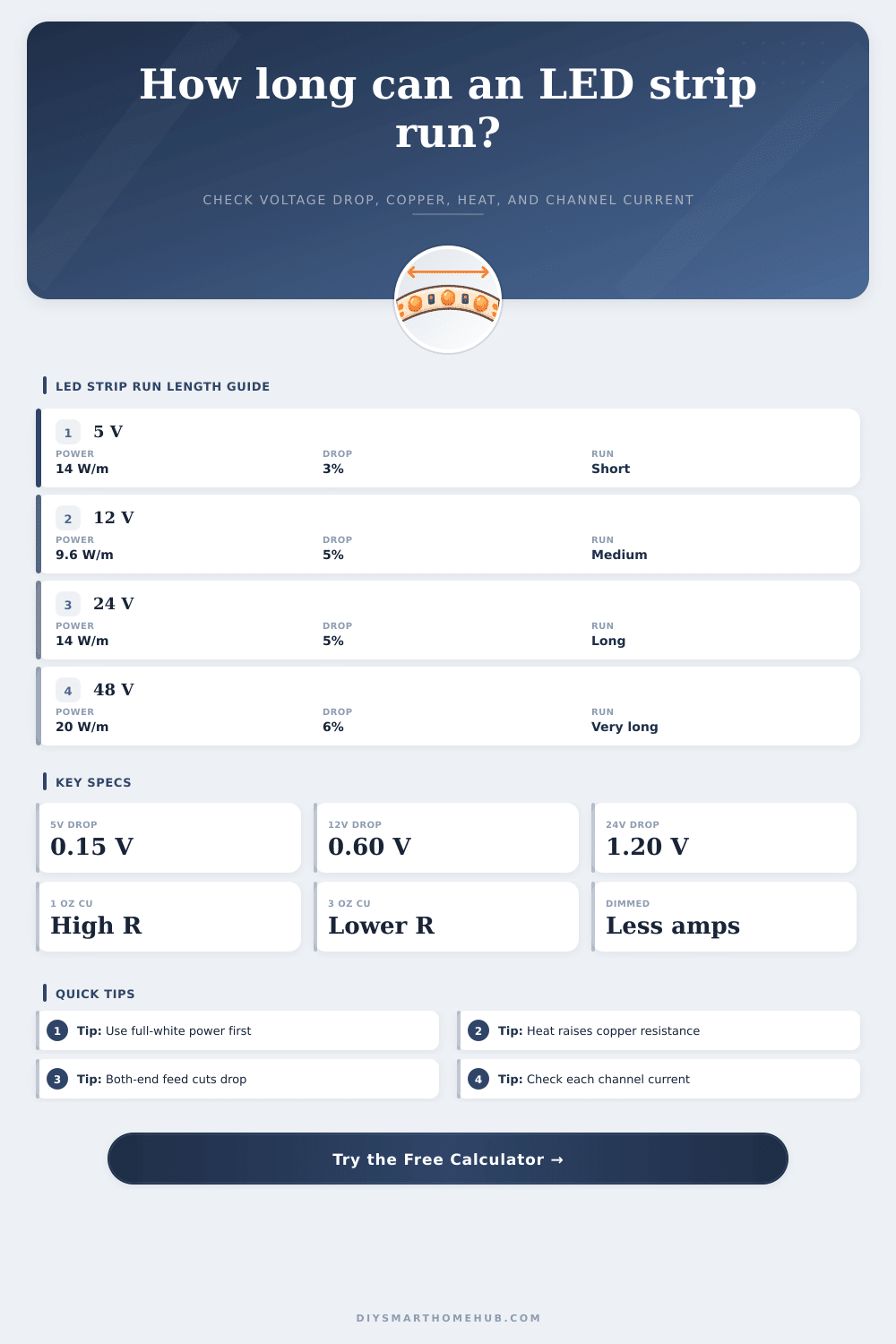
Your initial protection from this problem is Copper Weight. Light duty uses one ounce/square foot and Heavy duty may be as much as 3-4 ounces/square foot. Thicker copper acts like a wider highway for electricity. Less resistance mean a lower drop in voltage over longer distances. As you can see from the reference table, higher copper weight will increase the maximum run distance that can be used without seeing dark areas. For heavy density addressable pixels or higher power COB strips go with heavier copper. Yes it’s more expensive initially but avoids dark areas later on.
In addition to material selection, how you feed it makes a difference. If you feed power on only one end, then all electrons must travel the entire length. This means they’re piling up fast. Feeding power on both ends divide the load. Because length increases resistance in distributed loads (geometrically), each section is now effectively half as long and voltage drop will be significantly lower. This is a simple geometric advantage that takes little more effort, just make sure you have access to both end of your cabinet or cove.
Many guides gloss over another complication: ambient temperature. When copper heat up, it becomes a poor conductor of electricity. Heat can build up rapidly if you place an LED strip inside a tight ceiling cove with a plastic diffuser sealing it off. This heat raises the copper’s resistance, triggering a feedback loop. Increased resistance lead to increased heat. This extra heat raises the resistance again and results in even more voltage drop. By allowing you to account for derating factors and ambient temperature, the tool does all this for you. In a warm environment, lower your estimated run length. It is better to have shorter sections than one long section that slowly loses color accuracy or flickers.
RGB (or RGBW) setups have another hidden bottleneck: channel current limits. Based off solely on voltage drop, you may reason that you should of be able to easily power a twenty-four-volt strip ten meters long. However, if your controller only puts out two amps per color channel, then you reach that limit long before it’s a voltage problem. The RGB circuits pulls current independently from red, green and blue. Make sure you inspect the max current rating of each channel on your amplifier or dimmer. Going beyond will overheat your control electronics and lead to premature failure.
There are no free lunches when it comes to lighting design: you’re trading off heat versus performance, complexity versus cost, and distance versus brightness. That sweet spot can be calculated. Do your homework. Account for the warmest days of summer. Consider the age of your components. Leave a little headroom. The hottest evening mood lighting isn’t all that bright, so plan for the brightest day you’ll ever experience. Respect the laws of simple physics. It’s a good place to begin if you want your light source to stand up to scrutiny.
The heat in the air and the resistance in the wire affect performance. Do you want it patched together at the end or looking like a pro from the start?