LED Strip Voltage Injection Calculator
Estimate LED strip voltage drop, feed spacing, injection point count, branch current, and feeder-wire loss from strip length, voltage, watts per meter, copper gauge, feed style, dim level, and parallel branches.
Voltage Drop And Injection Result
| Strip Type | Typical Voltage | Power Range | Current Signal |
|---|---|---|---|
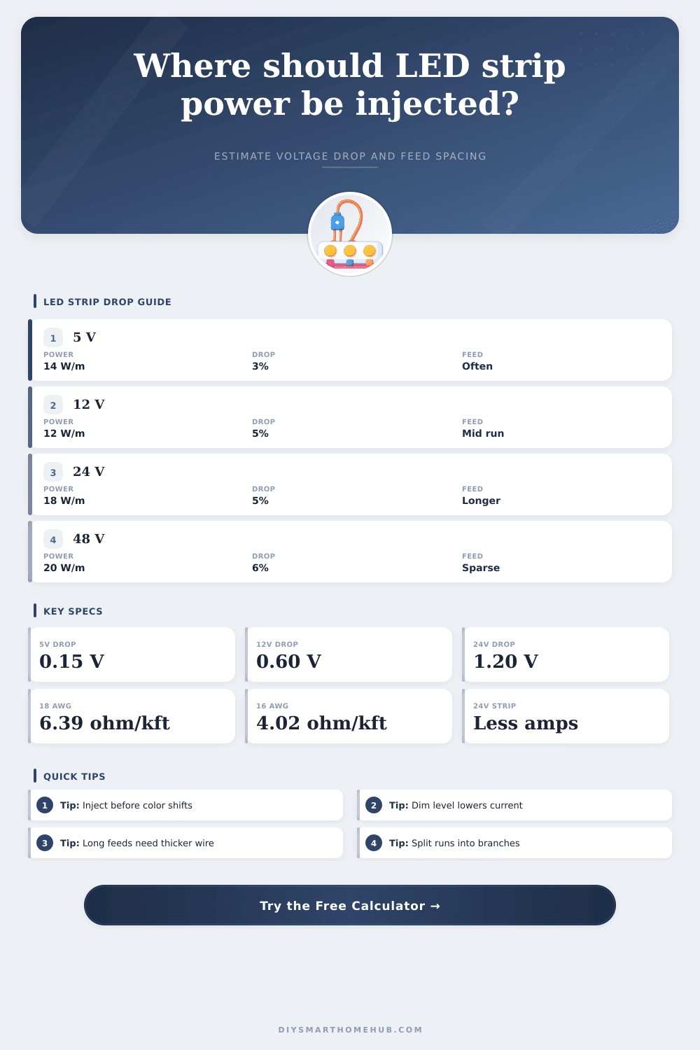
| 5 V addressable pixels | 5 V | 9 to 18 W/m | High current; inject often. |
| 12 V analog RGB | 12 V | 7.2 to 14.4 W/m | Moderate current; check color shift. |
| 24 V white COB | 24 V | 10 to 20 W/m | Lower current for long coves. |
| 48 V linear strip | 48 V | 12 to 25 W/m | Longest practical feed spacing. |
| Copper Gauge | Single Wire Resistance | Pair Resistance | Planning Use |
|---|---|---|---|
| 22 AWG | 16.14 ohm/1000 ft | 0.1059 ohm/m | Short low-current jumpers. |
| 20 AWG | 10.15 ohm/1000 ft | 0.0666 ohm/m | Small cabinet feeds. |
| 18 AWG | 6.385 ohm/1000 ft | 0.0419 ohm/m | Common LED strip injection wire. |
| 16 AWG | 4.016 ohm/1000 ft | 0.0264 ohm/m | Longer branch feeds. |
| 14 AWG | 2.525 ohm/1000 ft | 0.0166 ohm/m | Higher-current bus wiring. |
| 12 AWG | 1.588 ohm/1000 ft | 0.0104 ohm/m | Main low-voltage trunk runs. |
| Feed Style | Strip Drop Formula | Injection Count Logic | Best Fit |
|---|---|---|---|
| Single feed at start | I/m x R/m x L² / 2 | One feed per branch | Short low-current strips. |
| Feed at both ends | I/m x R/m x L² / 8 | Two feeds per branch | Medium runs with reachable end. |
| Center feed | I/m x R/m x L² / 8 | One feed at branch center | Symmetric room coves. |
| Start plus interval injections | Tail uses I/m x R/m x S² / 2 | Start feed plus repeated interval feeds | Runs where only one bus side is available. |
| Interval plus end feed | Between feeds uses I/m x R/m x S² / 8 | Feeds at start, interval, and end | Best for high-current long runs. |
| Example Run | Typical Inputs | Likely Injection Pattern | Watchpoint |
|---|---|---|---|
| Desk edge pixels | 2 to 3 m, 5 V, 14 W/m | Start and end feeds | 5 V drop becomes visible quickly. |
| Kitchen under cabinets | 4 to 6 m, 12 V, 9.6 W/m | Start plus one mid feed | Separate cabinet gaps change branch length. |
| Living room cove | 10 to 18 m, 24 V, 14 W/m | Parallel branches with interval feeds | Keep each branch balanced. |
| Pixel wall strips | 5 to 8 m, 5 V, 18 W/m | Frequent bus injections | Data layout may not match power layout. |
| Patio accent line | 15 to 25 m, 24 V, dimmed | Interval plus end feed | Lead wire drop can dominate. |
Wires dissipate electrical energy (voltage drop) while they conduct electricity. An LED strip has very fine copper wiring as paths. And they has limits. As electricity flows along that trace, some of it gets lost as heat. The greater the current and the longer the run, the more voltage goes bye-bye before hitting an LED chip. Even at five volts you may notice a difference in light output after a foot or so. At forty-eight volts maybe you won’t find anything wrong until twenty feet away.
The trick is mostly understanding what is actualy being measured. First you define the physical world in which the project exists. How long is it? What’s the amperage demand per meter? For most of us this mean grabbing the rated watts off the box. Good enough for a starting point. But if you’re going to run the lights at half intensity (a.k.a. Dimmed) then your amp requirement go way down. The calculator lets you account for this dimming factor. Why does this matter? Because lighting up something with full whiteness demands much higher amps than say, a soft amber evening scene. So if you size your power injection points around the worst case scenario, you’ll never have any flicker/shutdown problems when you want to blow them all out at max brightness for a party night.
How to Stop Voltage Drop in LED Strips
Next, we come to the wiring decision. That’s where things go wrong most of the time. Twenty-two gauge wiring look perfectly respectable in the hardware store aisle but it blocks current along long runs. Wire gets thicker and provides less resistance per foot. For example, eighteen gauge is popular as an average sweet-spot for residential injection leads. When you start pushing power around a whole room or even through a whole wall, sixteen or maybe even fourteen gauge are needed. The chart on the page explains this well. As the gauge goes up, the resistance per pair go down. You want lower resistance so voltage at the far end is closer to what came off the supply.
This refers to feeding style. A single-end feed will have a sharper drop off curve. Lights closer to the source will be brighter and those towards the tail fades out. Feeding from both ends or injecting power at regular intervals flattens that curve. This means the voltage remain relatively constant along the run. For installations such as a long hallway, running multiple parallel branches (rather than one giant feed) will often work better. Because there is less current flowing through each branch, the voltage drop decrease dramatically.
The enemy here, however, is color consistency. Color temperature changes before brightness does. If the voltage drops by only a little bit, you may not be able to see it with your eyes because the light won’t dim noticeably, but it will change color from neutral white to warm yellow. This breaks the illusion of seamless glow. By checking the voltage at the worst point, you can also confirm that all the LEDs is getting enough juice for their rated color output, even the ones furthest away.
So I went about planning. Until you’ve tried to retape some LEDs in a completed ceiling cove, it all seems like overkill. Squeezing your arm up there and hoping you don’t lose a driver… ouch. Do it once right and you save yourself hours of headaches. A road map. It tells you how big of wire to purchase and where to tap for power. All you have to do is spend a couple more bucks on some beefier copper and trust the numbers. Which isn’t much but man does it make a diffrence.
In many ways, lighting design is all about expectations vs. Physics. There’s no cheating resistance. You can only get around it with sufficient materials and smarter topology. What the calculator doesn’t do is pass judgment on those decisions. It simply presents you with a view of the tradeoffs. Once the numbers match the look you want, the lights will perform precisely as imagined. And that preparedness is what makes you confident. It is better to measure twice and inject power once rather than hunting for shadows after installation.