PoE Distance Calculator
Estimate Ethernet PoE run length from device watts, IEEE power class, conductor gauge, pair count, source voltage, minimum device voltage, and cable temperature.
PoE Run Result
Formula Breakdown
| IEEE type | Common name | PSE watts | PD watts | Powered pairs |
|---|---|---|---|---|
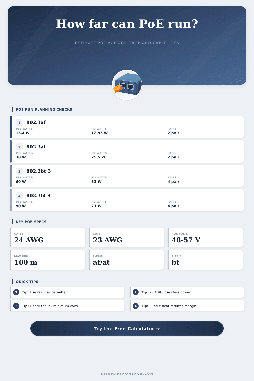
| 802.3af Type 1 | PoE | 15.4 W | 12.95 W | 2 pairs |
| 802.3at Type 2 | PoE+ | 30 W | 25.5 W | 2 pairs |
| 802.3bt Type 3 | PoE++ | 60 W | 51 W | 4 pairs |
| 802.3bt Type 4 | High-power PoE | 90 W | 71.3 W | 4 pairs |
| Cable option | Conductor | Resistance at 20°C | PoE distance note |
|---|---|---|---|
| Cat5e solid copper | 24 AWG | 25.67 Ω / 1000 ft | Normal 100 m planning cable |
| Cat6 solid copper | 23 AWG | 20.36 Ω / 1000 ft | Lower voltage drop for PoE+ |
| Cat6A solid copper | 23 AWG | 20.36 Ω / 1000 ft | Better thermal margin in bundles |
| Slim patch cable | 28 AWG | 64.9 Ω / 1000 ft | Use only for short patch runs |
| Device type | Typical watts | Common PoE class | Distance planning cue |
|---|---|---|---|
| VoIP phone | 3 W to 6 W | 802.3af Class 2 | Voltage drop rarely limits a normal run |
| Fixed IP camera | 7 W to 13 W | 802.3af Class 3 | Check night IR load, not idle watts |
| WiFi 6 access point | 15 W to 25 W | 802.3at Class 4 | 23 AWG improves margin near 100 m |
| PTZ camera heater | 45 W to 65 W | 802.3bt Class 7 | Needs 4-pair power and warm-cable check |
| Step | Formula | What it checks | Result used by |
|---|---|---|---|
| Class watts | PD watts compared with class budget | Whether the selected class can feed the device | Headroom card |
| Loop resistance | Ohms/ft x length x 2 conductors / pairs | Cable path resistance for PoE current | Voltage drop |
| Voltage drop | Current x loop resistance + connector V | How much source voltage is lost | Device voltage |
| Max distance | Allowed drop / current / path resistance | Longest run before PD voltage is too low | Distance card |
The infrastructure is simple because Power over Ethernet combines electricity and data on a single twisted pair. Distance become a factor with electricity since it loses voltage traveling down a line due to resistance. The distance calculator provided above does all the math for you after you provide gauge of your cabling and how much wattage your device pulls. You won’t have to guess if your run will hold up under environmental heat loads.
Most people consider feet of distance, but electrons care about resistance. To keep electrons flowing a standard Cat5e cable has a resistance value per thousand feet that limits them. As you increase the amount of current going through wire to support a high demand device, you reduce its voltage. Eventually the voltage reaches less than the devices require and it resets. Often this occurs even though switch lights up green showing everything ok because the voltage at the other end might not be sufficient.
How to Stop PoE Cable Problems
Finally, there’s an easy way to tweak your calculations for real world scenarios: swapping out your cable type. For example, thicker cables (like a 23AWG Cat6 compared to a 24AWG) has lower resistance. That means more voltage over longer distances. You should also factor in temperature… As copper loses conductivity at higher temperatures. If your wires is buried in your attic or running through a conduit, that heats up the cables and decreases conductivity. Add a derate factor here too. It recognizes that a wire performs different under a desk versus a cold warehouse floor.
These tweaks matter if you’re planning for reliability beyond just getting connected at the get-go. Remember that type of device itself has some power requirements. A VoIP phone doesn’t require much. It will likely never see any effects from voltage drop unless cable is cut. However, a PTZ camera with lights (night vision) and a heater draw far more power. Higher power = higher voltage drop down the length of the cable.
Older versions of PoE didn’t push as much power. That’s gentle on the wire. Newer high-power ones can move quite a bit of wattage. But they do so poorly across very warm, thin, or long cables. The table on the page above show the classifications’ budgets and number of pairs being used. If you push too much power through fewer pairs, you will lose some of that power to heat before it reaches the device.
Voltage margin also suffers from connector loss. Each time we connect something (crimping a connector, using a keystone jack in a patch panel) there’s a tiny bit of resistance. It doesn’t sound like much, and it isn’t individually. But those add up. Enter your allowance for friction in the calculator. You’re not just looking at the distance between two adult-sized sofa with wires, you’re looking at each connection point: each place where copper connects to metal.
Run the numbers and note the headroom value to see how much margin you have before the device struggle. If the calculation is close, congratulations! Your system works now, but will likely fail as soon as the device pulls a little extra current, or the room gets just a few degrees warmer. The point of planning for PoE is to not find the longest possible length, but instead manage your expectations accordingly.
If the math has your run at two hundred feet, make it one hundred eighty and give yourself a buffer. Thicker cable will cost you more up front, but save you from having to troubleshoot dropouts down the line. When a heatwave hits and your cameras start going offline, cheap cable makes the numbers look good on paper. Remember, you’re not just buying a connection, you’re buying reliability.
If you’re running a long run of wire to something, remember that it’s carrying both power and data at the same time and there will be loss over distance. You can use the calculator and your knowledge of physics behind it to help minimize voltage drop. Planning for the above variables and treating your cable with respect prevents devices from failing or going wonky.
Actually, you should of planned better.