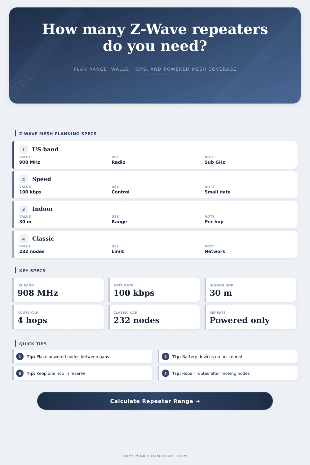
Z-Wave Network Range by Repeaters Calculator
Estimate powered repeater count from route distance, wall attenuation, floor changes, existing mesh helpers, Z-Wave device load, and desired route margin.
Sub-GHz mesh for small control packets. Powered nodes repeat; sleeping battery sensors generally do not.
Common for lights and sensors. Mains-powered routers build the mesh, while sleepy end devices conserve battery.
IPv6 low-power mesh. It uses border routers to connect the Thread mesh to home IP networks.
Matter can run over Wi-Fi, Ethernet, or Thread; it is not a radio repeater layer by itself.
| Spec | Planning value | Calculator use | Placement meaning |
|---|---|---|---|
| U.S. classic radio band | 908.42/916 MHz sub-GHz | Protocol reference | Lower frequency generally penetrates common walls better than 2.4 GHz links. |
| Classic PHY speed | 9.6/40/100 kbps, plan around 100 kbps capable gear | Control traffic only | Z-Wave is meant for commands and sensor states, not video or high-bandwidth data. |
| Indoor hop range | About 30 m / 98 ft per hop | Baseline range | Real homes reduce this with walls, cabinets, panels, mirrors, appliances, and floors. |
| Classic network size | 232 nodes per classic network | Capacity load | The hub, powered nodes, battery nodes, and new repeaters all count as nodes. |
| Classic mesh route | Plan for no more than 4 repeating hops | Hop risk check | Keep a reserve when possible so route repair has an alternate path. |
| Obstacle | Model loss | Typical examples | Range planning note |
|---|---|---|---|
| Drywall or wood partition | 3 dB each | Interior walls, hollow doors, cabinets | Usually manageable, but several in a row shrink usable hop distance. |
| Dense barrier | 9 dB each | Brick, block, concrete, foil insulation, metal door | Place a powered node on the near side and another on the far side when possible. |
| Floor transition | 7 dB each | Subfloor, joists, ducting, tile, radiant layers | Stairs, outlets, and hall switches often make better vertical mesh bridges. |
| Route margin | 10% to 30% | RF reserve for seasonal and load changes | Higher margin recommends more repeaters before the path becomes unreliable. |
| Device type | Repeats? | Best placement | Planning note |
|---|---|---|---|
| Powered plug-in repeater | Yes | Midpoint between hub and weak edge | Dedicated repeaters are easy to move during route tuning. |
| Powered switch or dimmer | Yes | Hallways, stairs, rooms between endpoints | These are often the strongest everyday Z-Wave backbone nodes. |
| Battery sensor | No | Endpoint only | Door, window, leak, and motion sensors usually sleep and do not repeat traffic. |
| Battery lock or FLiRS device | No backbone repeat | Near a powered beaming-capable node | Locks need nearby powered support because they cannot stabilize distant routes alone. |
| Scenario | Span | Obstacles | Common repeater plan |
|---|---|---|---|
| Same-room plug or switch | 15-30 ft / 5-9 m | 0-1 light walls | Direct route or existing powered node nearby. |
| Apartment entry lock | 40-70 ft / 12-21 m | 2-4 drywall walls | One powered node near the entry side of the path. |
| Garage tilt sensor | 60-110 ft / 18-34 m | Dense door, wall, appliance, or floor | One or two powered nodes between hub and garage. |
| Long house edge | 120-180 ft / 37-55 m | Many walls and one floor shift | Two or three powered repeaters spaced along the route. |
| Basement or outbuilding edge | 140-230 ft / 43-70 m | Concrete, metal, and vertical loss | Three or more powered helpers; classic hop limit may constrain the plan. |
A smart lock gets installed. The LED blinks red. You think: Damn, something broke at the house. Nope. House is fine.
Your radio path hit a brick wall and gave up, making you assume the house was broken. And then everyone learns how wireless protocols aren’t magic. How they’re physics. Physics cares about distance, density, and what is between them.
Why Your Smart Lock Signal Fails
In United States, Z-Wave operates over sub-GHz frequencies. This means it can absorbs through walls like drywall better than Wi-Fi. But it also has its own limits. Once you know the layout of your home, the calculator above do all the math for you. It saves you from having to do hop calculations and attenuation coefficient guessing.
So what moves the signal? The answer will take you far, because that’s the first thing to understand: powered devices are what make the mesh. Battery devices don’t. That’s where so many folks miss it. You could put out five door contacts and a half-dozen motion sensors all over your living room. If you don’t plug one of them into an outlet, no one is going to see them. They’ll wake up, send their data and return to sleep. They won’t forward any traffic for others. The battery sensors won’t help get the signal from your thermostat upstairs in the bedroom to your hub down in the basement. You need some sort of repeater on that journey, like a plug-in repeater or a smart switch.
It’s all about distance, but not the kind depicted on a floorplan. For radio signals, it’s the shortest possible route. It almost never resembles a straight line from point A to B. Drywall penetrates easily. Metal lath? Not so much. Thick wooden door frames? Nope. Foil-faced insulation? Not so much. Uh-huh. That’s where the loss values comes into play. These represent the amount of signal that will get lost en-route based off the material type. By entering the number of walls separating the controller from the weak device, you’re essentially instructing the calculator as to how many decibels worth of signal strength will be lost along the way.
Each interior wall may deduct just a few decibels worth of signal. Passing through a floor transition will incur a higher price (since the signal must pass vertically through subflooring and joists). Brick and concrete block act as dense barriers that’ll kill off any hope of a hop.
You should also consider hops. In classic Z-Wave networks there is a hard limit on how many times a message will be relayed. Pushing a route to the max number of relays makes your network brittle. If a single node goes offline or loses power, it may break the entire path. Having a reserve margin is a little thing that matters. It leaves the system some room to reroute if a device fails. The tool allows you to set this reserve. This setting influence how many extra repeaters it then recommends. Having a conservative margin is like buying one more plug today so you don’t troubleshoot a dead zone next month.
Another limitation is capacity. There’s only so many nodes for classic Z-Wave. And it’s not a limitless cloud! You don’t want to fill your big house up with dozens of switches and sensors without knowing where you’re at in terms of reaching that limit. The calculator will display your load percent. That’ll help you know what to buy and when, before you hit a wall you can no longer scale over.
And then there’s placement. The real world meets theory here. Don’t put all of your repeaters around the hub. That puts a big fat cloud of signal around the controller, this leaves the corners of the house in the dark. Spread them out. Use them as natural choke points, such as stairwells or hallways. They help bridge the gaps between rooms.
What about an outbuilding? Is it a garage? Treat that as a hard zone. Concrete floors and metal doors is hostile to radio waves. Odds are good you’ll need a dedicated repeater in the garage. It helps bounce the signal to a tilt sensor.
This is where people get all jacked up on it. No need for a signal analyzer. Think of a logical path from A to B. Find the longest run in your house. How many walls? What’s dense? What else powered equipment sits on that run? Stick a device or two in there. If the signal makes it to the end, you’re good. Drop out? Stick another one half way between the last good spot and the dead spot. Do that again till it sticks.
It is simple. And only works because you quit trying to treat battery sensors as an infrastructure piece. Endpoints. Not bridges. Clear that in your mind.
Once the signal can take a clear run across the house it works better. Force it through a brick wall? That doesn’t work well at all. You should of checked the signal strength first.