LED Strip Voltage Drop Length Calculator
Estimate strip current, feed-wire loss, copper-trace drop, safe powered section length, and practical voltage injection spacing for 5V, 12V, and 24V LED strip layouts.
| Step | Formula | What it checks | Planning note |
|---|---|---|---|
| Power density | watts per meter or watts per foot | Strip load along length | Use maximum channel load for sizing |
| Segment watts | W = power density x length | Watts per powered section | Brightness and margin are applied |
| Current | I = W / V | Amps carried by feed and copper | Lower voltage means higher current |
| Voltage drop | Vdrop = I x R x length | Feed wire and strip copper loss | Round-trip feed resistance is counted |
| Injection spacing | spacing = longest section under drop limit | Maximum run before the next feed | Derate reduces allowable spacing |
| Wire size | Ohms per 1000 ft | Loop ohms per meter | Best use |
|---|---|---|---|
| 24 AWG | 25.67 | 0.1684 | Very short low-current leads |
| 22 AWG | 16.14 | 0.1059 | Short cabinet jumpers |
| 20 AWG | 10.15 | 0.0666 | Small accent zones |
| 18 AWG | 6.39 | 0.0419 | Common LED feed wire |
| 16 AWG | 4.02 | 0.0264 | Longer or higher-current feeds |
| 14 AWG | 2.53 | 0.0166 | Main low-voltage bus runs |
| Project | Typical voltage | Typical load | Voltage-drop habit |
|---|---|---|---|
| Under-cabinet task strip | 12 V or 24 V | 9 to 15 W/m | Feed at cabinet breaks when possible |
| Addressable pixel strip | 5 V | 18 to 30 W/m | Inject often, especially at full white |
| Ceiling cove lighting | 24 V | 10 to 20 W/m | Use a bus and multiple feed drops |
| High-density COB strip | 24 V | 16 to 28 W/m | Watch feed wire current on long runs |
| Media wall backlight | 12 V | 7 to 14 W/m | Feed corners or split into branches |
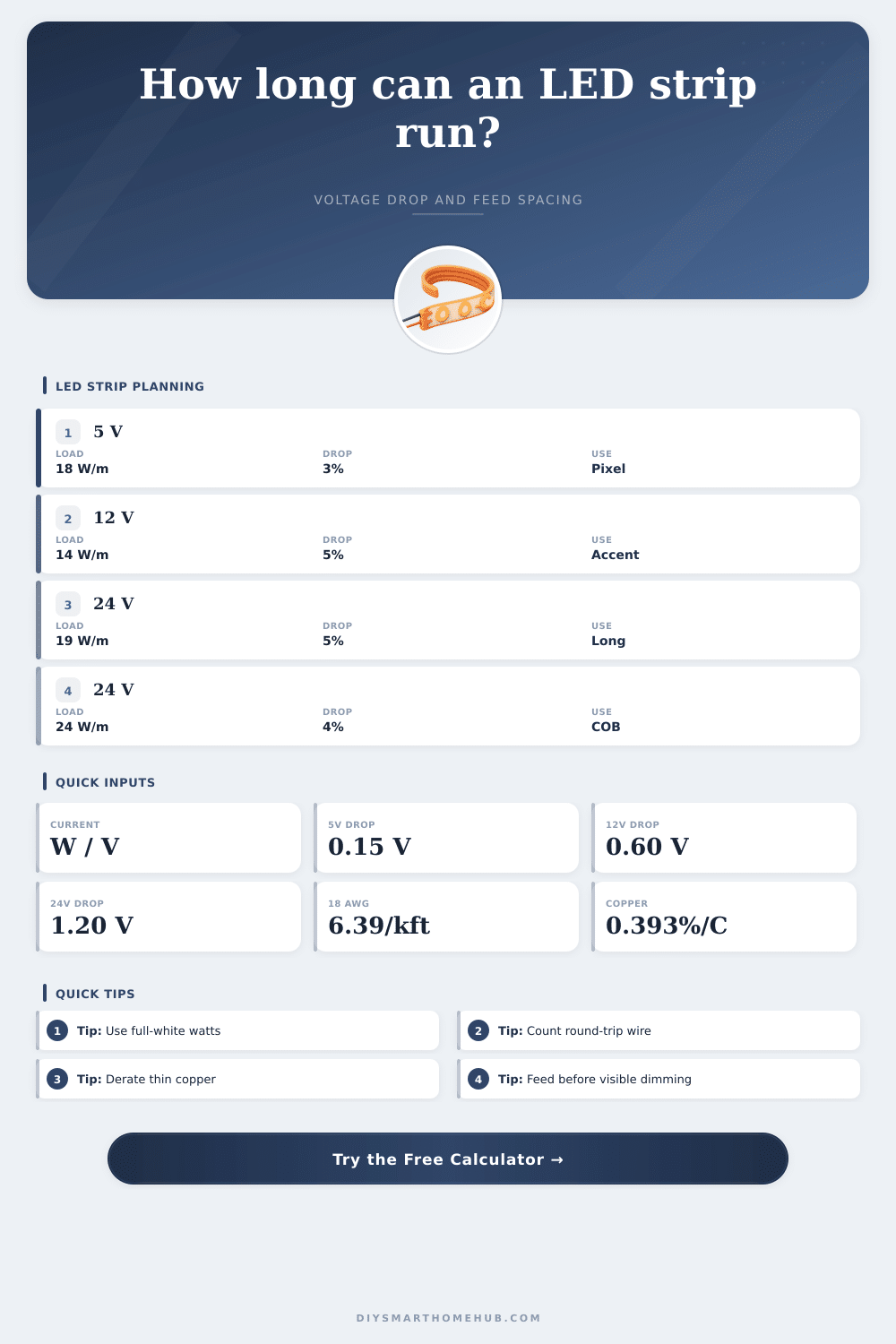
LED Strips will dim at the end of runs: You might have seen this. The strip starts off very brightly from the power source then fades down. That’s an issue with low voltage lighting systems fighting electrical resistance.
The calc helps ensure that your lights stay evenly lit by estimating the loss in current and wire. It’s a matter of simple physics. Electricity flows around resistance and the voltage gets lost doing so. Resistance increases with every inch of wire as electricity travels further. The higher the current then more voltage you will lose over distance. For example, pushing more current than 24V or 48V does in 12V systems.
Why LED Strips Get Dimmer at the End
If you only feed power to one end of a 5V addressable pixel strip, the brightness appear uneven. You need to know these measurements. This is because the amount of current that passes down the feed wire isn’t equal to the amount that actualy powers the LEDs on the strip itself. That’s relevant, as voltage drop isn’t linear. The first LED in line receives full current while the rest receive it only through copper traces that lead to them. It’s not a single bulb at the end of a string; it’s a spread-out load.
When most installers calculate watts for their power supplies they forget about wire size between the supply and the strip. Long distances, such as across a room to a cabinet, can reduce the supply voltage by a volt or two before it even gets to the LED connector if you’re using thin 24 AWG wire. Strip trace loss is separated from feed wire loss in the calculator. You’ll see exactly where your voltage are going.
To future proof your design, use derating to avoid headaches. Snap connector contact resistance is never included on data sheets… It’s cheap and adds to copper resistance which itself goes up as temps rise. A 10-20% derate margin allow for these realities of life. Enclosure warmth degrades over time; design with a buffer so you’re not dim when you install, but bright in five years.
The useful result you’re after is injection spacing. That’s the distance between your power feeds that will maintain voltage drop at or below your desired value. If you’re hanging something critical to color (like a media wall), stick with 3%. Ambient cove lighting could go as high as 5% and no one would notice. Depending on the type of strip and the voltage you select, the tool spits out a maximum spacing value.
The math is very different for dual-end feeding versus one-end feeding. For example, feeding both ends of a section effectively doubles the length of cable the current pass through, which cuts the maximum voltage drop in half. The longer your ceiling cove, the more money you can save by dividing the run into multiple short sections with a feed at each end. This is better than using a thicker gauge of wire fed from a central point.
The other issue is with high density COB strips that pull lots of power per meter. Even at 24V they’ll have high current. If the bus wire isn’t really heavy gauge or you don’t have lots of injection points, it’ll noticeable dim in the center portions when fully loaded. The calculator accounts for this by changing to your selected trace resistance profile.
Aim for even light levels without making the installation too complicated. If you can reach more meters on a given voltage, don’t feed every meter. Don’t guess. Learn from reference specs how various voltages performs, and follow the numbers where they lead you, both for junction points and in deciding what size wires to use.
Good lighting dissapears into the architecture. Bad voltage drop attracts attention to itself. Plan to avoid that fade before it happens.