LED Tape Cut Point Calculator
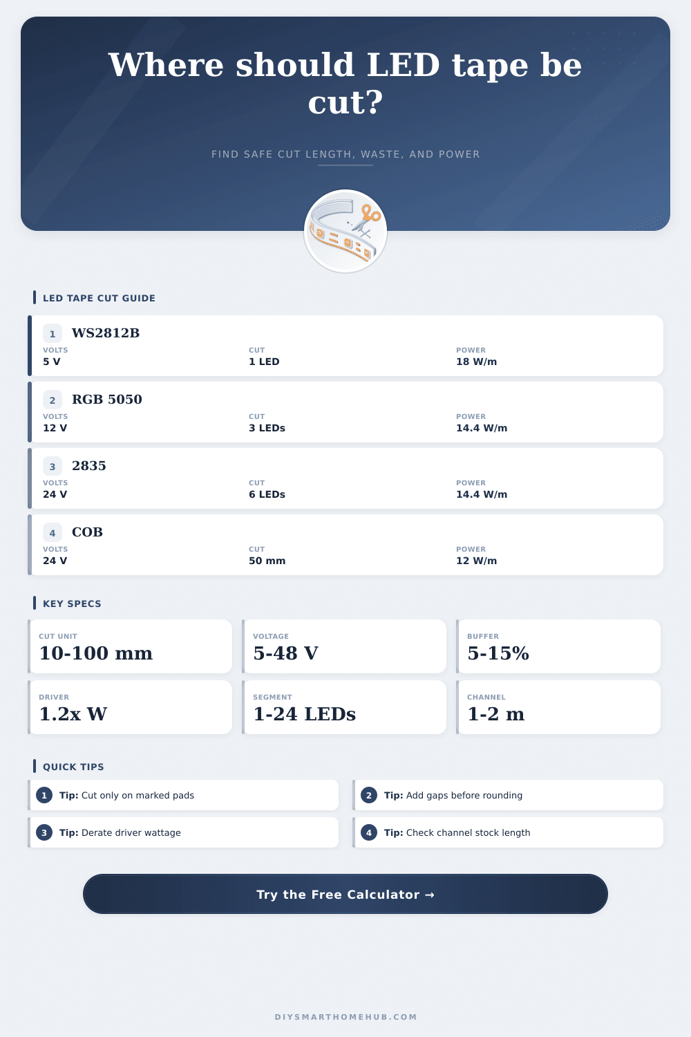
Round a target LED tape run to the nearest safe cut mark, then check usable lit length, segment count, waste allowance, channel pieces, power draw, and current.
Cut plan results
| Option | Total tape | Usable lit length | Result vs target |
|---|---|---|---|
| Under | 0 | 0 | 0 |
| Item | Formula | Calculated value | Planning note |
|---|---|---|---|
| Power | Length x W/m | 0 W | Use driver headroom |
| Tape preset | Voltage | Density | Typical cut interval |
|---|---|---|---|
| WS2812B addressable | 5 V | 30 LED/m | 33.3 mm, 1 LED |
| WS2812B addressable | 5 V | 60 LED/m | 16.7 mm, 1 LED |
| 5050 RGB tape | 12 V | 30 LED/m | 100 mm, 3 LEDs |
| 5050 RGB tape | 12 V | 60 LED/m | 50 mm, 3 LEDs |
| 2835 white tape | 12 V | 120 LED/m | 25 mm, 3 LEDs |
| 2835 white tape | 24 V | 120 LED/m | 50 mm, 6 LEDs |
| COB dotless tape | 24 V | 480 LED/m | 50 mm, 24 LEDs |
| RGBW 5050 tape | 24 V | 60 LED/m | 100 mm, 6 LEDs |
| Long-run white tape | 48 V | 120 LED/m | 100 mm, 12 LEDs |
Always verify the printed scissor marks on the actual reel; manufacturers can change pad spacing within the same broad tape family.
You’ve cut it out, double-checked your driver specifications, and re-measured the run. Still no lights on. Why? Because those copper pads along the strip aren’t aligned with a standard ruler. And most times it’s not even the tape; it’s the disconnection between what you want to reach and where the actual intervals of the circuit allow for clean cuts. Sections is marked to cut between, which causes internal circuits to break. Now you have open circuits or dead LEDs and a hosed reel. This calculator eliminates the gap. It transforms guesswork into a detailed plan before you bring out scissors.
Setting the desired length is really where the magic happens. Typically everyone begins with what you see in front of you, like I said above: how long do you want to have lit? Most people starts with the visible lit distance they want, say ten feet for a cabinet run. However, you must account for connection gaps, solder joints and corners. Without allowing for this, your “safe” cut point will actualy be shorter than your available install area. With this tool, you can specifies inches for each corner or joint. This provides slack in the wire as it bend around corners. It also accounts for the fact that tape does not bend perfecty snug. It is a small detail, but it is crucial when squeezing a rigid piece of aluminum into a tight space between walls.
How to Measure and Cut LED Strips Correctly
With that allowance figured out, it becomes a matter of determining the next good cut point. There’s no fudging with the spacing of LED strips, because they has fixed spacing between their copper scissor icons. That might be every 50 mm if they’re standard RGB segments or every 30mm if they are addressable. There is no rounding up or down here, getting them precisely on those spots ensures circuit continuity. The calculator will calculate how much you need all together then compare that to the interval (i.e., every 5th or 10th pixel) and give options. It’ll either provide a cut just short enough not to overlap your diffuser cover, or it will give you the nearest safe cut which might leave a tiny gap. Every option changes things very slightly, and the correct one really depends on what the tolerance on the housing itself are.
The same applies to cut logic. You don’t size your power supply based off the length you want but for the length you actualy have after finding the safe cut point. It may only be an inch or two but that mean different current draw and wattage load. This becomes important particularly when powering multiple string off one driver. And then there’s adding a ten percent waste buffer (because reels never roll out perfect straight and mistakes do happen). For common types of tape, those figures depends on both density and voltage and can be seen in the reference table on the page.
There’s also a layer of physical friction when it comes to installation. Depending on who you buy your aluminum channels from, they’re sold in fixed stock lengths (typically 1 or 2 meters). That means even with the best cut point for your LED tape, you must account for how those channels connects together. If you miter your corners you’ll waste aluminum. And if you don’t take care to make seamless joins where straight runs meet, you’re going to have visible seams. Expecting the hardware constraint early avoids frustration. It helps stop you from cutting out your tape only to realize you can’t stuff your perfectly cut-out strip into the casing you purchased.
It’s about accuracy, but not a frantic kind. Plan the route, then account for real-world joints and bends. Let the calculator do the rest, the in-between math. It will keep your power calculations true, but also maintain an unbroken circuit. When you cut, the lights comes up as planned. It illuminates the room rather than exposing your measurement mistakes.