Constant Current LED Driver Calculator
Size LED driver current, output voltage compliance, ripple current, power, and thermal derating for series strings or matched parallel strings.
Detailed electrical breakdown
| Topology | Use when | Compliance formula | Practical check |
|---|---|---|---|
| Buck constant current | Supply is higher than the LED string | Vstring worst + 2.0 V or 12% | Needs supply above output at all times |
| Boost constant current | Supply is lower than the LED string | Vstring worst + 8% regulation margin | Check maximum output voltage rating |
| Buck-boost constant current | Supply may be above or below LED string | Vstring worst + 12% conversion margin | Useful for battery and solar supplies |
| Linear constant current | Small strings with low noise demands | Vstring worst + regulator dropout | Heat rises with voltage difference |
| LED class | Typical drive current | Typical Vf range | Driver note |
|---|---|---|---|
| Indicator LED | 5-20 mA | 1.8-3.4 V | Linear current regulators are common |
| Mid-power SMD | 60-150 mA | 2.8-3.3 V | Use tight current matching for parallel rows |
| 1 W emitter | 300-350 mA | 2.9-3.6 V | Check thermal pad temperature |
| 3 W emitter | 600-700 mA | 3.0-3.7 V | Driver ripple should stay visibly low |
| COB module | 700-1500 mA | 18-54 V module | Confirm maximum output voltage range |
| High-power array | 2-5 A | 12-72 V array | Derating and heat sinking dominate |
| Driver spec | What to match | Good design band | Warning sign |
|---|---|---|---|
| Rated output current | Total string current | Equal to target or slightly lower | Higher than LED current rating |
| Output voltage range | Worst-case string voltage | String voltage inside min-max range | Cold Vf exceeds max output |
| Ripple current | LED current and dimming depth | 10-20% p-p for general lighting | Visible flicker or camera banding |
| Power rating | LED output watts plus reserve | 10-25% spare capacity | Driver runs at 100% in hot space |
| Thermal derating | Ambient around the driver case | Rated current after temperature derate | Derated current below target |
| Example | String design | Typical driver | Key constraint |
|---|---|---|---|
| 3 x 1 W accent | 3 in series, 350 mA | 350 mA, 9-12 V range | Cold Vf and 12 V headroom |
| Cabinet light bar | 4 parallel rows at 120 mA | 480 mA total, 10-14 V range | Current sharing between rows |
| COB downlight | 36 V class COB at 900 mA | 900 mA, 30-42 V range | Output voltage maximum |
| Grow panel chain | 12 diodes at 700 mA | 700 mA, 36-48 V range | Driver heat at high ambient |
| Path light string | 6 warm LEDs at 350 mA | 350 mA, 18-24 V range | Outdoor temperature swing |
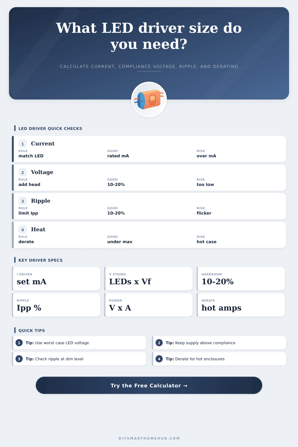
Every LED lighting project has a moment: the one where you double-check your voltage, find it barely meets the minimum required by driver, remember it’ll be even colder outside tonight, and you feel that spike of panic. This is because LED forward voltage increases at lower temperatures. That 32-volt string tested at room temp? Pushed 35 volts at dawn time. And if your driver can’t hit that higher voltage, it drop out of regulation. Flickers. Dimms. It is not because the LEDs failed. It happened because you didn’t plan for cold margin.
So how do you size these drivers? More then by simply summing the watts; you need to consider worst case before you pop open box. That’s where calculator on this page comes in; it does all the math for you as long as you specify that worst-case scenario. Rather than guesswork, enter forward voltage per LED into form. Also enter a percent tolerance to account for both cold starts and bin variation. This ensures you don’t buy a bigger power supply just because you don’t know exact values. This small input can save you money.
How to Choose the Right LED Driver
You must also account for how many parallel strings is there vs. How many LEDs are connected in series. Stringing LEDs in series adds voltage but maintain a consistent current throughout. Connecting LEDs in parallel add current without changing voltage. Mismatching these result in shutdowns for drivers or uneven brightness across LED. People tend to get tripped up here. Instead of multiplying desired current by the total number of LEDs, they should of used the number of parallel strings. The tool multiplies that value by number of parallel strings to calculate the total load.
But more than the number of volts involved, you also have to choose the correct topology. If your voltage source is greater then the string’s voltage, a buck driver will step down the voltage nicely. But what if you’re using a low-voltage battery system and must push voltage up to a higher-voltage LED array? You would use boost or a buck-boost configuration. The table on page makes this clear. It explains exactly how many volts of headroom each topology use simply to remain alive.
For instance, a linear regulator might appear to be a simple answer; it doesn’t switch frequencies and make noise. But it dumps excess voltage into heat. It is not very efficient for big arrays, but it is just fine for little indicator lights. A fire hazard for high-power arrays.
DIY lighting projects are subject to thermal derating… Drivers rated in a cool lab (25 degrees Celsius) aren’t necessarily reliable when your garage is 40 degrees in high summer. To model that, most constant current supplies exhibit reduced output with increased temperatures: some drop 1 to 2 percent per degree over a certain threshold. Designing without accounting for this slope will get your lights running just fine in winter… then failing miserably come July. The calculator requests your ambient temperature and applies a derating curve based off that value so you can see how much current you’ll actualy have on a hot day. It makes you design to real world conditions instead of ideal ones.
Another spec seems innocuous on paper, but kills your photos: Ripple Current. Small current oscillations from switching power supplies are bound to happen when using switchers. In general lighting applications, 20 percent peak to peak ripple is fine. But for any kind of film work, that ripple manifests as these awful looking banding artifacts on camera. Adjusting the allowable ripple percentage in tool will allow you to find drivers with tighter regulation loops, and help reduce it. Cost vs. Visual cleanliness is the catch here.
Power reserve provides breathing room The closer a driver is to being run at 100 percent of its capacity, the hotter it runs and shorter its life. Designing in 15 to 20 percent extra capacity provide for reserve, meaning the unit will be operating in its sweet spot; extending its life by quite a bit. The calculator does this for you automatically… Adding in that buffer, so you don’t mistakenly purchase a 10-watt driver and try to drive a 10 watt load. Seems like an easy mistake to avoid but guess what? People still make it.
Sizing your LED driver isn’t about getting the most out of something. It’s about managing limits. Once you consider topology headroom, thermal derating, and cold voltage spikes all at once, the math become clear very quickly. You no longer worry about components failing. Instead, you trust the system to remain stable throughout the temperature fluctuations. And that’s what gives professional lighting the appearance of effortlessness.