Battery Capacity Calculator Series-Parallel
Estimate a battery pack from series cells, parallel cells, cell amp-hours, nominal voltage, usable depth of discharge, load current, and per-cell discharge stress.
Calculation breakdown
| Chemistry | Nominal Unit | Typical Usable DoD | Capacity Planning Note |
|---|---|---|---|
| Li-ion NMC/NCA | 3.6 to 3.7 V cell | 70 to 85% | High energy density; current limits vary strongly by cell model. |
| LiFePO4 | 3.2 V cell | 80 to 90% | Common for solar, RV, and backup packs with stable voltage behavior. |
| Lithium titanate | 2.4 V cell | 80 to 95% | High-cycle specialty packs; lower cell voltage means more cells in series. |
| Lead-acid | 2.0 V cell | 40 to 60% | Usable capacity is often planned conservatively for longer service life. |
| NiMH | 1.2 V cell | 70 to 85% | Useful for smaller low-voltage packs where cell balancing is simpler. |
| LFP rack module | 51.2 V module | 80 to 90% | Use module Ah as the unit capacity and parallel modules for total Ah. |
| Capacity Step | Formula | Result Type | Why It Matters |
|---|---|---|---|
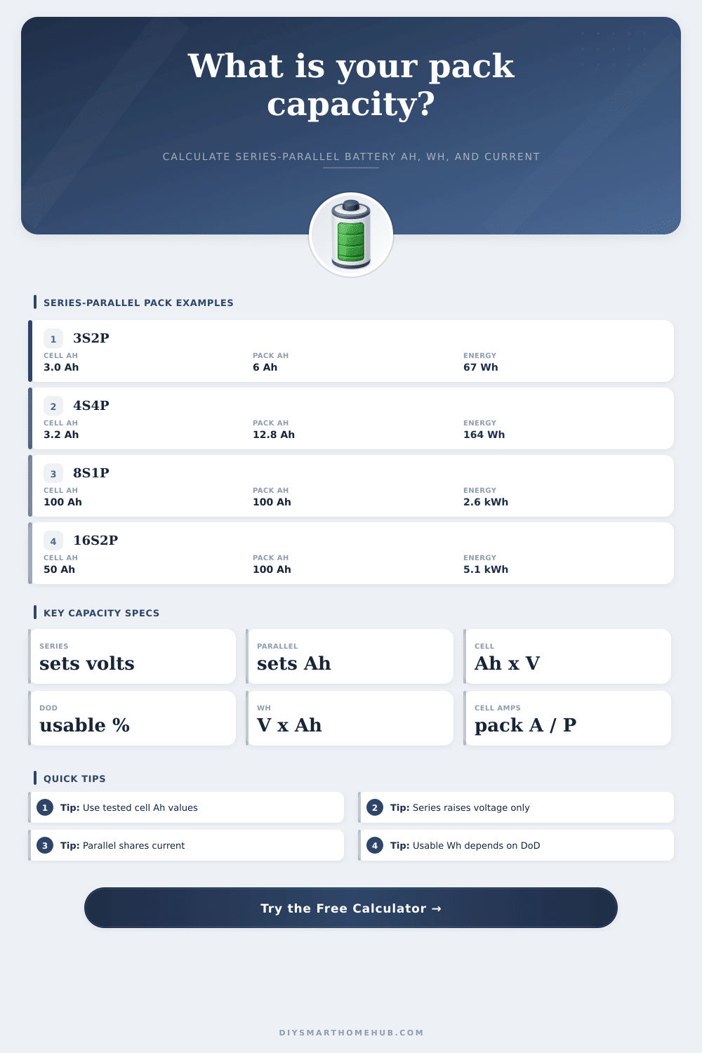
| Nominal voltage | Series cells x cell voltage | Volts | Series count changes voltage, not amp-hour capacity. |
| Total Ah | Parallel cells x cell Ah | Amp-hours | Parallel count changes pack capacity and current sharing. |
| Total Wh | Nominal voltage x total Ah | Watt-hours | Wh compares packs across different voltages. |
| Usable Wh | Wh x DoD x efficiency / reserve | Available energy | Separates nameplate storage from planned delivered energy. |
| Discharge per cell | Pack current / parallel cells | Amps per cell | Checks current stress for each cell or module in parallel. |
| Runtime | Usable Wh / load watts | Hours | Requires voltage x current to convert discharge into watts. |
| Example Pack | Inputs Used | Nominal Capacity | Usable Estimate | Best Calculator Use |
|---|---|---|---|---|
| 3S2P Li-ion | 3.7 V, 3 Ah cells | 11.1 V, 6 Ah, 66.6 Wh | About 49 Wh at 80% DoD and 92% efficiency | Router backup and compact DC packs. |
| 4S6P Li-ion | 3.7 V, 3.2 Ah cells | 14.8 V, 19.2 Ah, 284 Wh | About 222 Wh at 85% DoD and 92% efficiency | LED strips, camera shelves, and low-voltage automation. |
| 4S1P LFP | 3.2 V, 100 Ah cells | 12.8 V, 100 Ah, 1.28 kWh | About 0.97 kWh at 80% DoD and 95% efficiency | 12 V class home, shed, and solar loads. |
| 16S2P LFP | 3.2 V, 50 Ah cells | 51.2 V, 100 Ah, 5.12 kWh | About 3.89 kWh at 80% DoD and 95% efficiency | 48 V inverters and backup racks. |
| 24S1P lead-acid | 2.0 V, 200 Ah cells | 48 V, 200 Ah, 9.6 kWh | About 4.32 kWh at 50% DoD and 90% efficiency | Legacy UPS strings with conservative usable capacity. |
| Metric | Formula | Healthy Signal | Watch Point |
|---|---|---|---|
| Per-cell continuous current | Continuous pack amps / P | Below cell continuous rating | Parallel imbalance can raise stress on weak cells. |
| Per-cell peak current | Peak pack amps / P | Within cell pulse capability | Peak ratings depend on time, cooling, and voltage sag. |
| Pack C-rate | Pack amps / pack Ah | Lower C-rate for long runtime packs | High C-rate reduces usable energy and increases heat. |
| Capacity target gap | Usable Wh - target Wh | Positive margin | Negative margin means more P groups or higher Ah cells. |
Amp-hours only compare packs at the same voltage. Wh and kWh reveal the actual stored energy across 12 V, 24 V, 48 V, and custom battery packs.
A pack can have enough Wh but still ask too much current from each cell. Divide continuous and peak pack current by the parallel count.
Cells store energy. Wires convey energy. Configurations, power output. There’s danger in messing with batteries. They needs assembling with care.
Put them in series to increase voltage, put them in parallel to increase capacity. It all seems pretty straightforward but when you’re trying to figure out how long your emergency lights will last during a blackout it gets complicated. Most people starts with a target voltage because their inverter or motor require specific inputs. Your inverter might require 48-volts; adding amps won’t get you there. To obtain the target voltage you stack cells in series. This simply add the nominal voltages from each cell. Sixteen cells at 3.7 volts equals about 51 volts. That’s the typical output for today’s lithium packs.
How to Connect Battery Cells Safely
But that still doesn’t do anything for your runtime. Connecting in series only boosts voltage of the battery pack. Capacity lives on parallel strings. One cell with three amp-hours? Two in parallel = 6. Four in parallel = 12. The number of amp-hours multiplied by the number of parallel string equals total runtime. The calculator does all that for you (above).
Understanding how it works will help you avoid a pitfall. People often think, “I’m buying these giant high-capacity cells, so I don’t need as much physical space.” They forget that those big cells might not be able to keep up with the surge current that their device require. DIY packs has an issue with current sharing. Ideally, if I’m pulling 10 amps on a parallel bank of four strings, they’d each is drawing two and a half amps. Not so in practice; there are always subtle differences in resistances inside each cell, meaning one string ends up picking up most of the slack. Once that primary string reaches its thermal limit, it will throttle back (or fail), putting even more strain on the other strings. It starts a chain reaction. That’s why it is not enough to simply look at the watt-hour capacity and stare at it; you must also check your per-cell current against what the maker rates the cells for being discharge.
The usable energy, how deep you can discharge that battery pack… Makes all the difference. For instance, you could have a pack rated for one thousand watt-hours, yet use only eighty percent for good cycle life. That leaves you with eight-hundred. Then there are efficiency losses on your management system and wiring, which also eats up a chunk. Each little piece of that loss add up. The ten percent reserve buffer isn’t simply a matter of safety margin. It’s an insurance policy on those bad days when your charger misbehaves, or the sun clouds over your solar panels.
Your planning strategy is dictated based off chemistry. If you use lithium iron phosphate cells, you get a stable voltage curve, long life, and they are forgiving for off-grid storage. If you use NMC cells, you can pack more energy in a small space, but they requires tighter voltage monitoring. Then you’re golden. Lead acid (cheap but punishes heavy discharge) will make it obvious if you picked the wrong chemistry. Here’s that reference table on the page that spells this out: the typical usable percentage shifts depending than chemistry. If you pick the wrong chemistry, you’ll end up having to overbuild your pack size to compensate for wasted capacity you can’t access.
Your assumptions about how much you’re going to load it are only as good as the runtime estimate. For example, if your appliance has a variable power draw, assume the maximum sustained draw instead of startup spikes. This is the worst-case scenario from a battery perspective. It won’t empty the tank in a hurry, but it will immediately strain the wiring and fuses.
A battery is about balancing current capabilities vs voltage requirements. To get more capacity, you parallelize. For more voltage, you stack. And you should of leave some breathing room because life happens and reality will never be perfect. It’s not about storing electricity; it’s about giving you electricity in a reliable way that doesn’t burn your investment. Understand what you want to power, figure out the inefficiencies, and then let the math tell you how many cells you need. Plan for the worst day, not the best day, and it’ll work better.