Capacitor Bank Sizing Calculator
Estimate power-factor correction kvar from kW, starting PF, target PF, voltage, stage size, detuning allowance, current, and a discharge resistor hint.
⚡Power-factor correction presets
🔧Bank sizing inputs
Calculated capacitor bank
Formula breakdown
📊Capacitor bank and stage spec grid
📐Power factor correction reference table
| Starting PF | Target 0.95 | Target 0.96 | Target 0.98 | Use note |
|---|---|---|---|---|
| 0.70 | 0.691 kvar/kW | 0.729 kvar/kW | 0.837 kvar/kW | Heavy correction |
| 0.75 | 0.553 kvar/kW | 0.590 kvar/kW | 0.699 kvar/kW | Motor-rich load |
| 0.80 | 0.421 kvar/kW | 0.458 kvar/kW | 0.567 kvar/kW | Typical service |
| 0.85 | 0.291 kvar/kW | 0.329 kvar/kW | 0.437 kvar/kW | Moderate bank |
| 0.90 | 0.156 kvar/kW | 0.194 kvar/kW | 0.302 kvar/kW | Light correction |
🔌Voltage and current sizing table
| Bank kvar | 208 V 3-phase | 240 V 3-phase | 480 V 3-phase | 600 V 3-phase |
|---|---|---|---|---|
| 25 kvar | 69.4 A | 60.1 A | 30.1 A | 24.1 A |
| 50 kvar | 138.8 A | 120.3 A | 60.1 A | 48.1 A |
| 100 kvar | 277.6 A | 240.6 A | 120.3 A | 96.2 A |
| 200 kvar | 555.1 A | 481.1 A | 240.6 A | 192.5 A |
| 400 kvar | 1110.3 A | 962.3 A | 481.1 A | 384.9 A |
⚙Detuning and stage selection table
| Bank type | Input factor | Stage pattern | Best fit | Calculation note |
|---|---|---|---|---|
| Standard fixed | 0% | 1 stage | Stable load | Raw kvar rounded up |
| Standard automatic | 0% | 5 to 12 steps | Varying load | Use smaller first stage |
| 5.67% detuned | 5.67% | Equal steps | Light harmonics | Add reactor allowance |
| 7% detuned | 7% | Binary or equal | Common VFD mix | Check capacitor voltage |
| 14% detuned | 14% | Engineered steps | Stronger harmonics | Coordinate with study |
📋Common bank sizing examples
| Scenario | Load | PF change | Raw kvar | Possible bank |
|---|---|---|---|---|
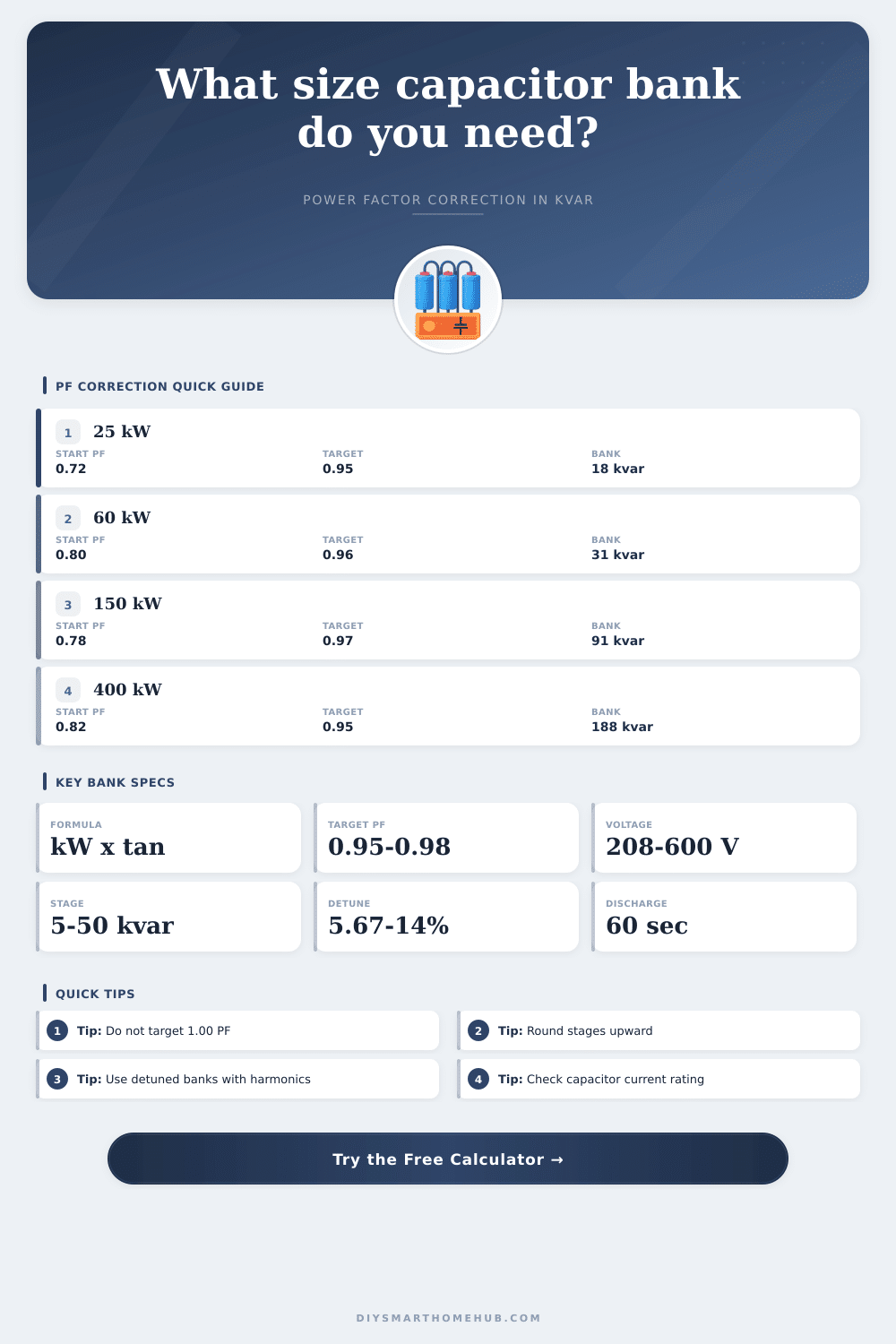
| Small workshop | 25 kW | 0.72 to 0.95 | 17.1 kvar | 4 x 5 kvar |
| Retail panel | 80 kW | 0.76 to 0.96 | 45.8 kvar | 5 x 10 kvar |
| HVAC plant | 120 kW | 0.78 to 0.96 | 74.2 kvar | 4 x 25 kvar |
| Cold storage | 300 kW | 0.82 to 0.96 | 122.1 kvar | 6 x 25 kvar |
| Light manufacturing | 450 kW | 0.79 to 0.95 | 214.0 kvar | 5 x 50 kvar |
💡Calculation tips
We are all familiar with that low hum in the breaker panel that seem to get louder during hot afternoons. That’s not nothing; it’s frequently an indicator of bad power factor, meaning you’ve got electrical system that’s needlessly working hard to move electricity around. Utilities don’t like it (they have to create more current to deliver the same amount of useful work), and guess who pays for that waste with surcharges on their bill?
Typically, fixing it require adding some capacitor banks, but sizing those right is a cost/space/electrical-safety balancing act. When you plug in actual power of your load and your desired efficiency percentage, the calculator will do the work for you. It will calculate amount of reactive power that should be added to bring lagging angle toward one while avoiding extra cost from equipment purchases.
How to Fix Power Factor Problems
People tend to shoot for an ideal power factor of exactly 1.0. Don’t do this. You’ll only do it when the load peaks, so when the load reduces after correcting for its highest point, the capacitors may cause system to become leading. This increases the voltage, which can blow out sensitive electronics and trip protective relays. A better goal is somewhere between 0.95 and 0.98. There’s plenty of leeway here to accommodate dips in load (lights dimming, motors cycling off) while remaining safely within bounds.
The other key parameter are the stage size. If your load is all over the place from hour to hour, you don’t necessarily need one huge bank. By having smaller steps, the controller can bring in/out individual capacitors that closely match current demand curve (the “actual” vs. “correction” value). With this tool, it’s easy to see how much each additional stage contributes to overall correction value. A handful of big steps will suffice for a small shop where machines are running consistently. But if you’re in a retail situation, with lighting/AC coming on/off as shoppers enter/exit, then finer detail avoids over-correcting when no-one’s around. Match building’s behavior with the equipment.
Things get complicated further with harmonics. Today’s facilities are littered with switching power supplies and variable frequency drives distorting waveform. Standard capacitors can amplify these harmonics. This causes resonance problems which will cause overheated wiring or blown fuses. Now, let’s look at detuning reactors. By adding impedance into the circuit, they move resonant frequency off the common harmonic orders. When you choose your reactor percentage on the calculator, it adjusts the kvar rating based off this factor. For most mixed-load environments, choosing 7 percent detuning gives you enough correction but also blocks fifth harmonic, which is a safe starting point.
And of course, don’t neglect safety. Even if you disconnect a capacitor it will retain a charge. Open up a panel too early and that charge will deliver a nasty jolt. To get rid of the charge, capacitors has discharge resistors that gradually drain it away. It’s one little detail in the design process but critical when someone else maintains system later on. Here is a suggestion for the right size resistor to quickly discharge the capacitor down to a safe voltage level in under a minute.
To put some of these numbers in perspective, have a look through their reference tables located on the same page. You’ll see how much reactive power you need for every kilowatt of starting load depending on your initial level of efficiency. For example, going from an efficiency of.80 to.95 will require much larger bank compared to going from.85 to.95. This is why it’s so important to measure your own baseline beforehand. Don’t guess, because you’ll either get an oversized bank that wastes space and money or an undersized one that doesn’t cut down on your penalties at all.
Also note: the current drawn will depend on voltage rating of the equipment. In higher voltage systems, the same kvar draws less current, requiring smaller breaker and conductor sizes. The calc does this automatically depending if you have a 3 phase or 1 phase power service. If a reactor is being used, it raises the effective voltage across capacitors themselves; make sure your capacitor voltage ratings matches your system. (It’s simple math, but get it wrong and you’ll overheat the connection).
At its core, that’s what power factor correction is all about: Respect for the grid (and your wallet). It turns waste current into useful capacity. Not everyone needs to be an engineer to grasp the concept, though understanding numbers requires a certain degree of faith. Unless you know how to begin, stick with the presets. From there, adjust the inputs to reflect your one-of-a-kind load profile. Aim for steady efficiency while being careful to avoid over-correction. When everything’s balanced, you will keep that low hum coming from the panel away.